C PRODUCT OUTLINE > 2. OVERALL COMPOSITION
C-14
d-Color MF4003/MF3303
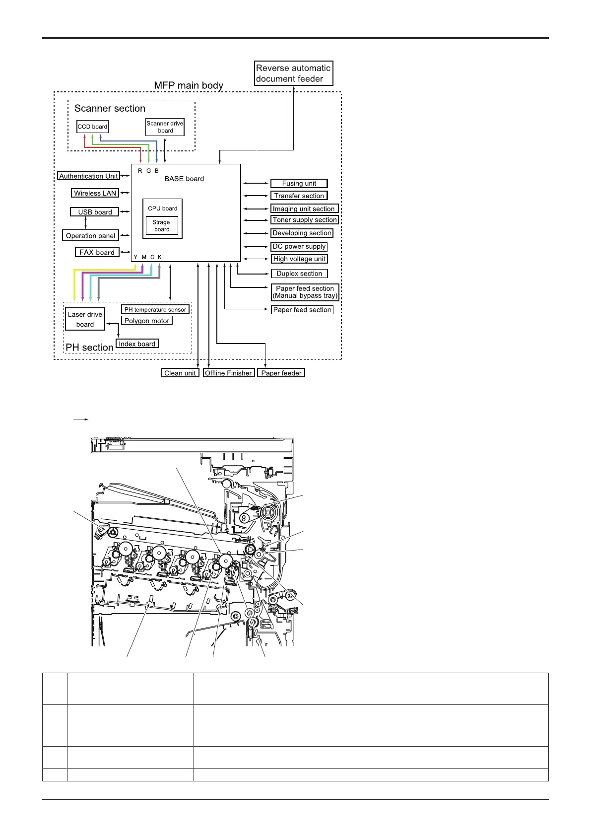
2.4CONTROL BLOCK DIAGRAM
2.5IMAGE CREATION PROCESS
[3]
[2][1]
[4]
[6]
[7]
[8]
[9]
[10]
[11]
[12][5]
[1] Photoelectric conversion The light reflected off the surface of the original is separated into different colors using the color
filters (R, G, and B); CCD then converts it into a corresponding electric signal and outputs the signal
to the IR imaging processing section.
[2] Printer image processing • The electric signal is converted to digital image signals. After going through some corrections,
video signals (C, M, Y, and K) are output to the printer image processing section.
• D/A conversion will be performed after the VIDEO signals (Y, M, C, K) are corrected. This data
will control the emission of the laser diode.
[3] Photoconductor The image of the original projected onto the surface of the photoconductor is changed to a
corresponding electrostatic latent image.
[4] Photoconductor charging Supply DC (-) charge on the photoconductor.

 Loading...


