d-Color MF4003/MF3303
I SERVICE MODE > 5. Machine
I-8
• If width A or B is longer than the target, make the setting value smaller than the current one.
• If width A or B is shorter than the target, make the setting value greater than the current one.
7. Press the Start key to let the machine produce a test pattern.
8. Check width A and width B on the test pattern.
9. If width A or width B is outside the target, change the setting again and make a check again.
10. If width A and width B fall within the target, touch [END].
5.3.6Tray Printing Position: Tip
• To change and adjust image printing position at vertical scanning direction by each feed. (to adjust the timing starting from the roller
connection up to start of transfer output). It is not applicable in case the job is fed at re-feed.
• To be used when [Printer Area-Leading Edge Adjustment] is not enough for full adjustment (as such case that image printing position gets
deviated due to pattern of each feed.)
• Adjustment is made for plain paper.
NOTE
▪ [Printer Area-Leading Edge Adjustment] should be made within target.
▪ Image printing position at vertical scanning direction is adjusted based on the combination value of this setting figure and
[Printer Area-Leading Edge Adjustment] figure. In case the value does not fall in the setting range, the figure should be rounded
to the minimum or maximum value.
Target Setting range Default setting
4.2 ± 2.0 mm -3.0 mm to +3.0 mm (in 0.2 mm increments) 0.0 mm
<Procedure>
1. Set the targeted tray with plain paper, and select the feed tray.
2. Press the Start key to let the machine produce a test pattern.
3. Check the dimension of width A on the test pattern.
4. If width A falls outside the target, change the setting using the [+] / [-] key.
• If width A is longer than the target, make the setting value smaller than the current one.
• If width A is shorter than the target, make the setting value greater than the current one.
5. Press the Start key to let the machine produce a test pattern.
6. Check the dimension of width A on the test pattern.
7. If width A is outside the target, change the setting again and make a check again.
8. If width A falls within the target, touch [END].
5.4Scan Area
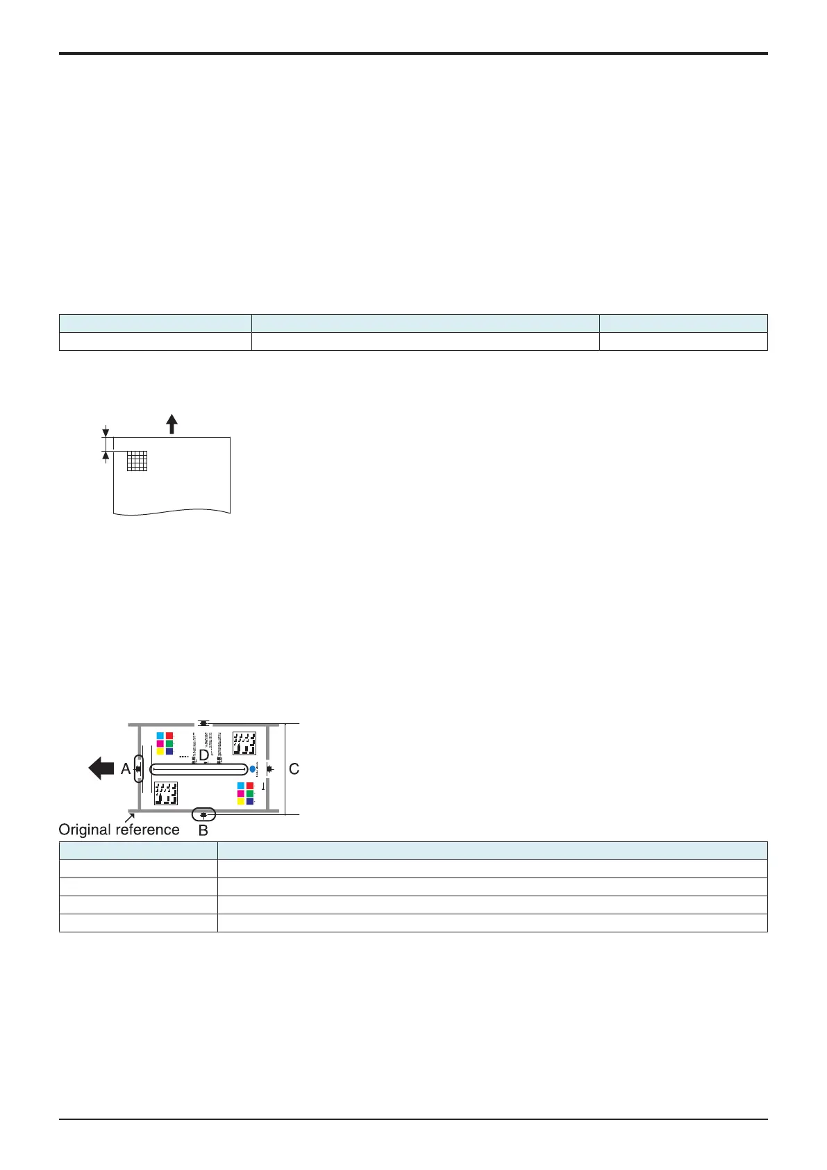
5.4.1Test chart
• Use the following test chart for the adjustment of the scanner section.
• If the test chart is not available, a scale may be used instead.
Y M C
C
M C Y Y M
Color is “hue”,
lightness is “value”,
saturation is “chroma”:
this is the world of color.
Hue
P2 P2
The quality of color which can be
described by words such as red,
yellow, blue etc.
Value
The quality of color which can be
described by words such as light,
dark etc., relating the color to a gray
of a similar lightness.
Chroma
The quality of color which can be
described by words such as vivid,
dull etc., describing the extent to
which a color differs from a gray
having the same value.
P1
1.0
1.1
1.25
1.4
1.6
1.8
2.0
2.2
2.5
2.8
3.2
3.6
4.0
4.5
Y M C
C M
C Y Y M
1.0
1.1
1.25
1.4
1.6
1.8
2.0
2.2
2.5
2.8
3.2
3.6
4.0
4.5
Measurement position Adjustment item
A Image Position: Leading Edge
B Scanner Image Side Edge
C Main Scan Zoom Adj.
D Sub Scan Zoom Adj.
5.4.2Image Position: Leading Edge
• To adjust variations in mounting accuracy and sensitivity of the scanner home sensor and in mounting accuracy of the original width scale
by varying the scan start position in the sub scan direction.
• When the original glass is replaced.
• The CCD board has been replaced.
• The scanner home sensor has been replaced.
NOTE
▪ Width A on the color chart and one on the test pattern are measured and adjusted so that the difference of width A satisfies the
the following target shown below.
▪ An adjustment must have been completed correctly of [Leading Edge Adjustment] of the [Printer Area].

 Loading...


