P THEORY OF OPERATION > 1. d-Color MF4003/MF3303
P-22
d-Color MF4003/MF3303
1.6.4Imaging unit (developing)
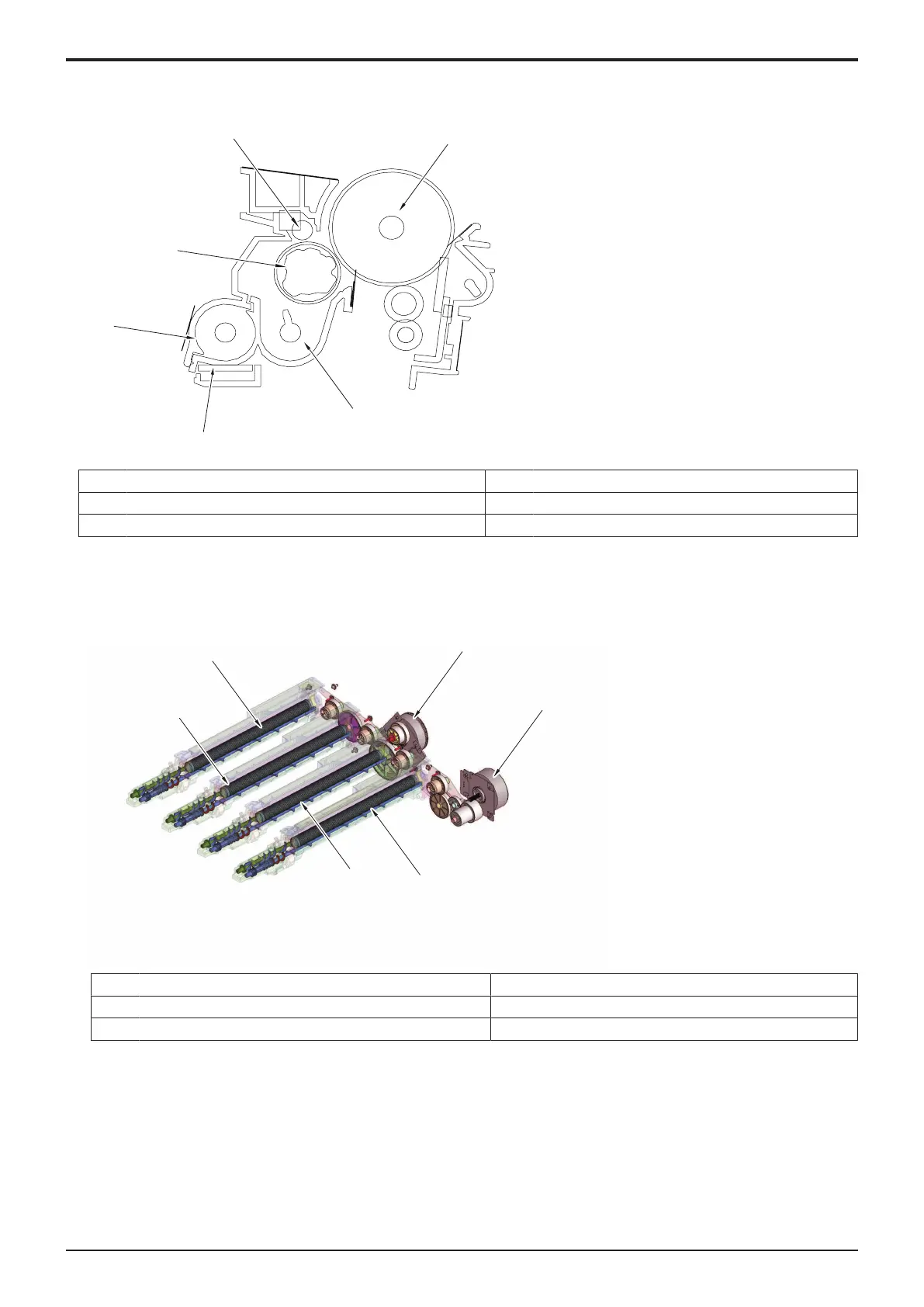
(1)Configuration
[1] Photoconductor [2] Toner supply screw 2
[3] TCR sensor [4] Toner supply screw 1
[5] Developing roller [6] Doctor shaft regulator
(2)Drive
(a)Developing section/Y, M, C, K drive mechanism
• Rotation of the main motor transmits drive to the developing drive gear, which drives the developing roller/K.
• Rotation of the color PC motor transmits drive to each developing drive gear, which drives the developing rollers/Y/M/C.
[1] Color motor (M2) [2] Main motor (M1)
[3] Developing roller/K [4] Developing roller/C
[5] Developing roller/M [6] Developing roller/Y
(3)Operation
(a)Developer flow
1. Toner replenished via the toner replenishing port located at the front side of the machine is fed to the toner supply screw 1.
2. The developer is conveyed toward the rear of the unit, while being agitated and electrically charged, by the toner supply screw 1.
3. The TCR sensor installed on the underside of the imaging unit detects toner-to-carrier (T/C) ratio during this time. If the T/C ratio is
lower than a predetermined value, toner is replenished.
4. The developer, fed to the rear of the developing unit, is conveyed further onto the toner supply screw 2.
5. The developer fed to the toner supply screw 2 is conveyed onto the developing roller because of the magnetic pole positioning of the
developing roller.
6. The doctor blade then controls the height of the developer brush to ensure that the developer on the developing roller levels out.

 Loading...


