I SERVICE MODE > 13. State Confirmation
I-68
d-Color MF4003/MF3303
13.10Load Check
• To check each device (electric component) for proper condition by individually activating the load associated with the device.
• To identify faults at the time of troubleshooting.
NOTE
Take note of the following during the load check mode.
• No malfunction is detected and no count is taken of consumables life and related items.
• Two or more devices (motors, clutches, solenoids, and fans) cannot be checked simultaneously.
• Detection of proper installation of various types of units and waste toner box does not function. During the check procedure,
therefore, make sure that the unit in question is installed correctly or yet to be installed.
<Procedure>
1. Open the front door, lower front door or the right door.
2. Touch [Start Load Check].
3. Close the door opened on step 1.
4. Referring to the load check list, enter a check code.
5. Referring to the load check list, enter a multi code.
6. Press the Start key.
• When pressing the Start key, the specified load is activated. The Start key blinks in orange.
7. Check the load operation and output of signals.
8. Press the Stop key to stop the check operation and check the result.
NOTE
▪ Depending on the type of load being activated, after the lapse of the specified time or after the transition to the specified
state, the corresponding device automatically stops working.
▪ When ‘NG’ is displayed, check the wiring and connectors.
9. To check another load or signal output, repeat steps 4 to 8.
10. Turn OFF the main power switch and turn it ON again more than 10 seconds after.
NOTE
▪ To exit from the load check mode, be sure to turn off and on the main power switch.
At the point when you display [Service Mode] -> [State Confirmation] -> [Load Check], MFP enters into load check mode.
Regardless of whether load check is actually performed or not, the main power switch must be turned off and on to exit from load
check mode.
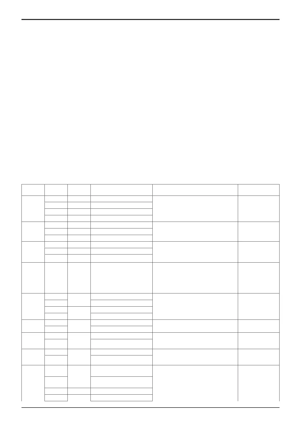
13.10.1Load check list
Check
code
Multi code Symbol Load name Operation outline Note
20 1 CL3 Tray 1 paper feed clutch Drives the specified clutch. -
2 CL3/2 Tray 2 paper feed clutch
3 CL3/3 Tray 2 paper feed clutch
4 CL2 Bypass tray paper feed clutch
21 1 CL2/2 Tray 2 transport clutch Drives the specified clutch. -
2 CL2/3 Tray 3 transport clutch
2 CL4 Registration clutch
23 4 M6 Tray 1 lift-up motor Starts the lift-up operation. The motor stops
when the upper limit
sensor or lower limit
is detected.
5 M2/2 Tray 2 lift-up motor
6 M2/3 Tray 3 lift-up motor
24 1 CL1 1st transfer pressure clutch Starts the pressure/release operation of the
1st transfer belt.
NOTE
Be sure to perform the release operation
whenever the pressure/release operation
has been performed. *1
-
28 11 M1/2 Tray 2 drive motor high speed Drives the motor at the specified speed.
14 Tray 2 drive motor low speed
16 M1/3 Tray 3 drive motor high speed
19 Tray 3 drive motor low speed
32 1 M7 Polygon motor high speed Drives the motor at the specified speed. -
2 Polygon motor low speed
40 1 M1 Main motor high speed Drives the motor at the specified speed.
NOTE
Perform with the transfer belt removed.
-
4 Main motor low speed
41 1 M2 Color motor high speed Drives the motor at the specified speed.
NOTE
Perform with the transfer belt removed.
-
4 Color motor low speed
42 1 FM1 Power supply cooling fan full
speed
Drives the specified fan. -
2 Power supply cooling fan half
speed
3 FM2 Machine cooling fan full speed
9 FM4 Clean ventilation fan full speed

 Loading...


