d-Color MF4003/MF3303
L TROUBLESHOOTING > 3. TROUBLE CODE
L-29
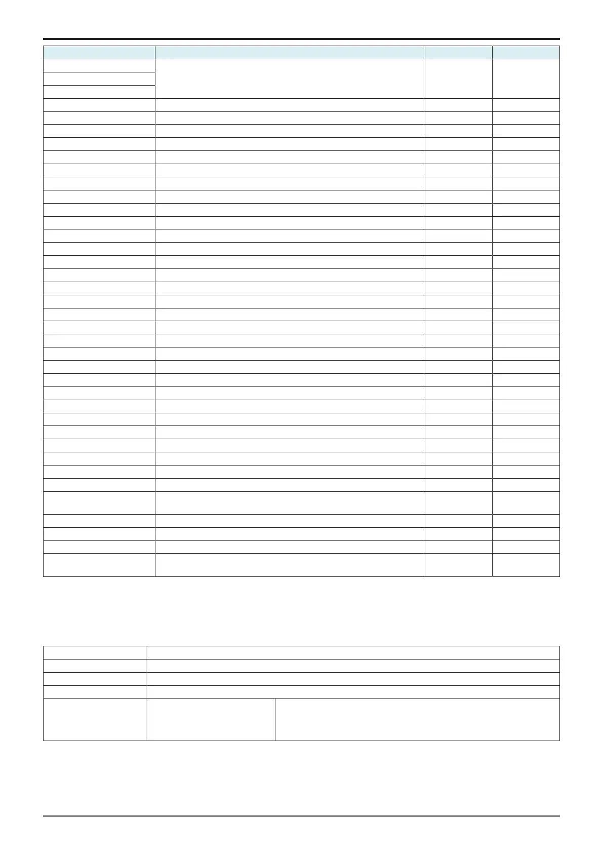
Trouble Code Contents Rank Self-diag. (Full)
CD601 Trouble related to security - -
CD602
CD603
CD701 Mechanical controller flash ROM writing error C -
CD702 Mechanical controller flash ROM device error C -
CD703 FW download communication fault C -
CDC## Trouble related to security - -
CDF50 ASIC image version failure C Target
CDF51 ASIC image version failure (back side) C Target
CDF70 ASIC image access failure C Target
CDF71 ASIC image access failure (back side) C Target
CDFA0 ASIC image error C Target
CDFA1 ASIC image error (back side) C Target
CE001 Abnormal message queue C Target
CE002 Message and method parameter failure C Target
CE003 Task error C Target
CE004 Event error C Target
CE005 Memory access error C Target
CE006 Header access error C Target
CE007 DIMM initialize error C Target
CE009 Memory resource shortage error C Target
CE011 Config. file access error at startup of FW C Target
CE013 Virus scan engine startup failure (8 GB storage) C Target
CE014 Virus scan engine startup failure (storage error) C Target
CE101 Browser finish detected C Target
CE201 Transmission operation log storage fault C Target
CE202 PDL interpreter error C Target
CE203 Unrecoverable error C Target
CE301 Referring incorrect memory C Target
CE302 Incorrect command C Target
CE303 Finished due to error inside Qt library C Target
CE304 Finished due to error outside Qt library C Target
CE305 Program forced to stop C Target
CED01 The authentication application information does not exist in the storage in
the enhanced server authentication state.
C Target
CEEE1 CPU board (MSC) malfunction C Target
CEEE2 Scanner section malfunction A Target
CEEE3 Base board (ENG) malfunction A Target
CF### Trouble code (CF###) is referred to as abort code.
For details of abort code, refer to “ABORT CODE”.
C -
3.7C0###
3.7.1C0103
Contents
Trouble type C0103: Tray 2 drive motor malfunction (When PF-P20 or PF-P21 is installed)
Rank B
Trouble detection condition The motor lock signal remains HIGH for a predetermined continuous period of time while the motor is turning.
Trouble isolation Tray 2
Relevant electrical parts <When PF-P20 or PF-P21 is
installed>
• Tray 2 drive motor (M1/2)
• Tray 2 PC control board (PCCB/2)
• CPU board (CPUB)
• Base board (BASEB)
Procedure
1. Check the connector between M1/2-PCCB/2 CN4 for proper connection and correct as necessary.
2. Check the connector between PCCB/2 CN1-relay CN24-BASEB CN21E for proper connection and correct as necessary.
3. Check the connector of M1/2 for proper drive coupling and correct as necessary.
4. Check CPUB for proper installation and correct as necessary.
5. M1/2 load check

 Loading...


