d-Color MF4003/MF3303
F DISASSEMBLY/REASSEMBLY > 4. d-Color MF4003/MF3303
F-24
13. Remove two screws [1], and remove the boss [2].
NOTE
▪ When installing the scanner unit, make sure that the boss [2] is
attached to the frame of the main body.
14. Remove the scanner unit [1].
15. To reinstall, reverse the order of removal.
4.3Boards
4.3.1Base board (BASEB)
1. Remove the rear cover.
F.4.1.3 Rear cover
2. Remove the CPU board.
F.4.3.3 CPU board (CPUB)
3. Remove the TPM board.
F.4.3.6 TPM board (TPMB)
[1] [4]
[4] [5]
[4]
[5]
[3] [2]
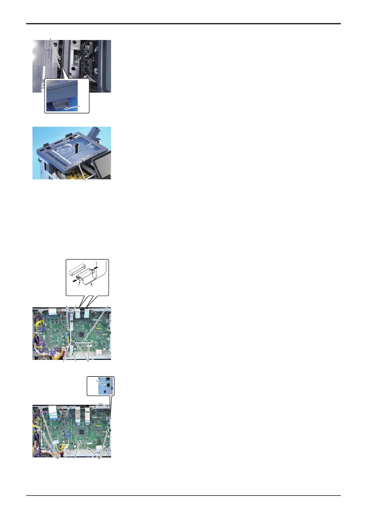
4. Remove the harness from the wire saddle [1].
5. Remove all connectors and flat cables.
NOTE
▪ When removing the flat cable [2], unlock the connector [3], and
remove the cable together with the connector.
6. Remove five screws [4], and remove two plates [5].
7. Remove nine screws [1], and remove the base board [2].
8. To reinstall, reverse the order of removal.

 Loading...


