d-Color MF4003/MF3303
L TROUBLESHOOTING > 16. IMAGE QUALITY PROBLEM
L-147
Step Section Check item Result Action
5 Developing section With the color of toner responsible for the abnormal
image, there is a positive contact between the
developing bias application terminals and the high
voltage unit connection terminals (Y: B4; M: B3; C: B2;
K: B1).
NO Clean or correct the terminal.
6 Connector connection Faulty connector connection the high voltage unit (CN1)
and base board (CN4E).
YES Reconnect the connector.
7 Write section Faulty connector connection the PH unit and base board
(CN13).
YES Reconnect the connector.
8 Service Mode -> Self-
diagnostic
Select [Service Mode] -> [State Confirmation] -> [Self-
diag.(Full)] and perform the function. Then, "NG"
appears.
YES Take relevant action
corresponding to the check item in
which "NG" has appeared.
NO • Replace the high voltage unit.
• Replace the PH unit.
• Replace the base board.
Scanner troubleshooting procedure
Step Section Check item Result Action
1 Black copy: Scanner
section
Foreign matter on scanner guide shaft. YES Clean and apply lubricant. *
2 Scanner moves smoothly. NO Replace the scanner motor.
3 • When original glass
is being used
• When DF is being
used: 1st side
None of the terminal pins of the connection cable
between the CIS module and the base board (CN6) is
bent and a positive connection is made.
NO Reconnect the connector.
4 • When original glass
is being used
• When DF is being
used: 1st side
Replace the connection cable between the machine and
the DF. This eliminates the trouble.
YES Replace the connection cable.
5 • When original glass
is being used
• When DF is being
used: 1st side
Select [Service Mode] -> [State Confirmation] -> [Self-
diag.(Full)] and perform the function. Then, "NG"
appears.
YES Take relevant action
corresponding to the check item in
which "NG" has appeared.
NO • Replace the CIS module.
• Replace the base board.
6 When DF is being used:
2nd side
Faulty connector connection the high DF CIS module
and base board (CN5).
YES Reconnect the connector.
7 When DF is being used:
2nd side
Replace the connection cable between the DF CIS
module and the base board. This eliminates the trouble.
YES Replace the connection cable.
8 When DF is being used:
2nd side
Shading correction surface of DF is dirty. YES Clean.
9 Service Mode -> Self-
diagnostic
Select [Service Mode] -> [State Confirmation] -> [Self-
diag.(Full)] and perform the function. Then, "NG"
appears.
YES Take relevant action
corresponding to the check item in
which "NG" has appeared.
NO • Replace the DF CIS module
assy.
• Replace the base board.
*: Apply HA-050E to the scanner guide shaft. HA-050E is a product manufactured by SUMICO LUBRICANT CO., LTD.
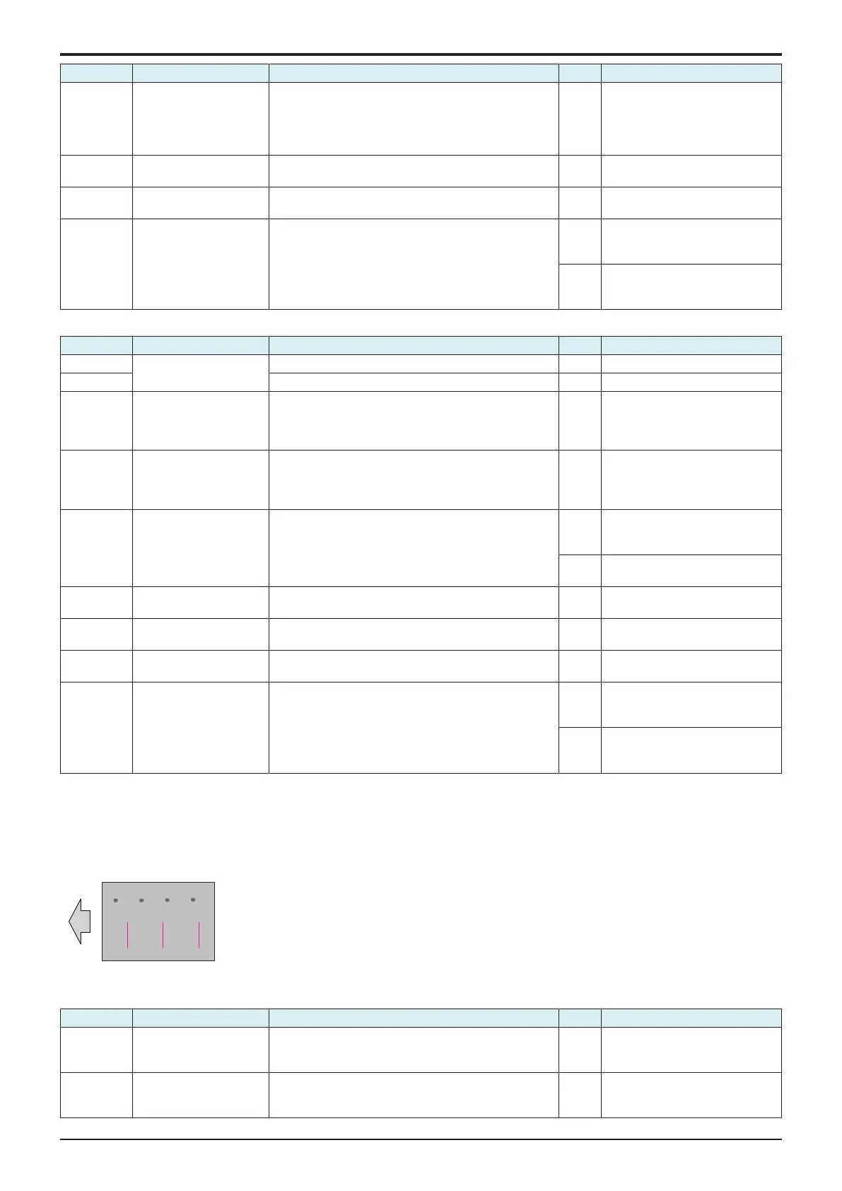
16.3.16Uneven pitch
Typical faulty images
The arrow in the exemplary image troubles indicates the paper feeding direction.
Initial troubleshooting procedure
Step Section Check item Result Action
1 Paper Setting The paper to be used for printing does not match the
paper type and size of paper setting selected on the
machine.
YES Make the paper setting again on
the machine.
2 Service Mode ->
Stabilizer
Select [Service Mode] -> [Imaging Process Adjustment] -
> [Stabilizer] -> [Stabilization Only] and the image
trouble is eliminated.
NO Go to the next step.

 Loading...


