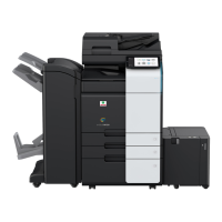
d-Color MF4003/MF3303
L TROUBLESHOOTING > 4. TROUBLESHOOTING USING SELF-DIAG. (FULL)
L-81
2. Correct the mounting of the upgrade kit (UK-221) or the connection of connectors if faulty.
3. Correct the mounting of BASEB or the connection of connectors if faulty.
4. Replace WLANB.
5. Replace BASEB.
4.20E5-12
Contents
Error code E5-12
Target device Various USB devices
Diagnosis item Authentication unit
Reason of error Connection failure
Parts defect
Relevant electrical parts Authentication unit
Base board (BASEB)
Corrective action procedure
1. Turn OFF the main power switch and unplug the power cord. Connect the power cord after 15 sec. or more, and turn ON the main power
switch.
2. Correct the mounting and connection of the authentication unit if faulty.
3. Correct the mounting of BASEB or the connection of connectors if faulty.
4. Replace the authentication unit.
5. Replace BASEB.
4.21E6-1, E6-2
Contents
NOTE
▪ When executing the Self-diag. (Full) after the trouble code (C6###, C91##) is displayed, the self-diagnosis may not complete. In
that case, finish the Self-diag. (Full) forcibly, and perform the troubleshooting against each trouble code.
▪ Turning OFF the main power switch will finish the Self-diag. (Full) forcibly.
Error code E6-1, E6-2
Target device CIS module
Diagnosis item E6-1 I/P image bus check (front side)
E6-2 Line RAM comparison (front side)
Reason of error E6-1 Image bus failure
E6-2 CIS sensor failure
Relevant electrical parts E6-1 CIS cable
CIS module (IR CIS)
CPU board (CPUB)
Base board (BASEB)
E6-2 CIS module (IR CIS)
Corrective action procedure
1. Turn OFF the main power switch and unplug the power cord. Connect the power cord after 15 sec. or more, and turn ON the main power
switch.
2. Correct the mounting of IR CIS or the CIS cable if faulty.
3. Correct the mounting of CPUB if faulty.
4. Correct the mounting of BASEB or the connection of connectors if faulty.
5. Replace the CIS cable.
6. Replace IR CIS.
7. Replace CPUB.
8. Replace BASEB.
4.22E7-1, E7-2
Contents
NOTE
▪ When executing the Self-diag. (Full) after the trouble code (C6###, C91##) is displayed, the self-diagnosis may not complete. In
that case, finish the Self-diag. (Full) forcibly, and perform the troubleshooting against each trouble code.
▪ Turning OFF the main power switch will finish the Self-diag. (Full) forcibly.
Error code E7-1, E7-2
Target device DF CIS module
Diagnosis item E7-1 I/P image bus check (back side)
E7-2 Line RAM comparison (back side)
Reason of error E7-1 Image bus failure
E7-2 CIS sensor failure
Relevant electrical parts E7-1 CIS cable
DF CIS module (DF CIS)
CPU board (CPUB)

 Loading...
