d-Color MF4003/MF3303
L TROUBLESHOOTING > 16. IMAGE QUALITY PROBLEM
L-141
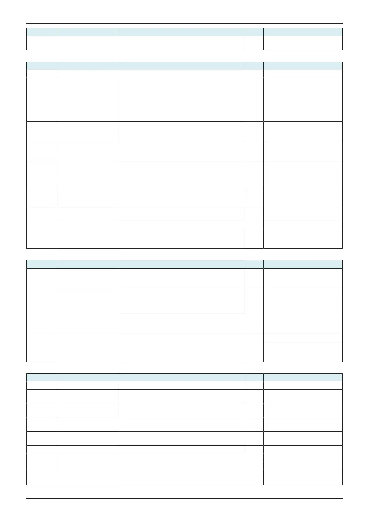
Step Section Check item Result Action
• Check the image after printing to determine which
color causes the abnormal image.
1-color troubleshooting procedure
Step Section Check item for the faulty color Result Action for the faulty color
1 Write section Dirt or foreign matter on the dust-proof glass of the PH. YES Clean the PH window.
2 Charging section Foreign matter on charging roller. YES Lightly wipe the surface clean of
foreign matter using hydro-wipe
(65AA-99##).
Note: Do not apply a strong force
to the surface of the charging
roller, as doing so can damage the
surface.
3 Photoconductor section There is a positive contact between the electrostatic
charger application terminals and the high voltage unit
connection terminals (Y: C4, M: C3, C: C2, K: C1).
NO Clean or correct the terminal.
4 Developing section There is a positive contact between the developing bias
application terminals and the high voltage unit
connection terminals (Y: B4; M: B3; C: B2; K: B1).
NO Clean or correct the terminal.
5 Service Mode -> TCR
data
Select [Service Mode] -> [State Confirmation] -> [Level
History 1] and the measured value is correct.
TCR-C, TCR-M, TCR-Y, TCR-K: normal value 5 to 8%
NO Select [Service Mode] -> [Imaging
Process Adjustment] -> [Manual
Toner Add] and perform the
function.
6 Service Mode -> Max
Image Density Adj
Select [Service Mode] -> [Imaging Process Adjustment] -
> [Max Image Density Adj] and make the necessary
adjustment, and the image trouble is eliminated.
NO Go to the next step.
7 Connector connection Faulty connector connection the high voltage unit (CN1)
and base board (CN4E).
YES Reconnect the connector.
8 Service Mode -> Initialize
+ Image Stabilization
Select [Service Mode] -> [Imaging Process Adjustment] -
> [Stabilizer] -> [Initialize + Image Stabilization] and
[Gradation Adjust], and the image trouble is eliminated.
YES Readjust.
NO • Replace the imaging unit.
• Replace the PH unit.
• Replace the high voltage unit.
4-color troubleshooting procedure
Step Section Check item Result Action
1 Transfer belt unit There is a positive contact between the transfer belt
application terminals and the high voltage unit
connection terminals (T1).
NO Clean or correct the terminal.
2 2nd transfer section There is a positive contact between the application
terminals of the 2nd transfer and the connection
terminals (T2) and ground terminal of the high voltage
unit.
NO Clean or correct the terminal.
3 Service Mode -> Max
Image Density Adj
Select [Service Mode] -> [Imaging Process Adjustment] -
> [Max Image Density Adj] and make the necessary
adjustment, and the image trouble is eliminated.
NO Go to the next step.
4 Service Mode -> Initialize
+ Image Stabilization
Select [Service Mode] -> [Imaging Process Adjustment] -
> [Stabilizer] -> [Initialize + Image Stabilization] and
[Gradation Adjust], and the image trouble is eliminated.
YES Readjust.
NO • Replace the transfer belt unit.
• Replace the high voltage unit.
• Replace the base board.
Scanner troubleshooting procedure
Step Section Check item Result Action
1 Original Original is damaged or dirty. YES Change the original.
2 Original Type Select [Copy] -> [Original Type] and change the setting,
and the image trouble is eliminated.
NO Go to the next step.
3 Basic -> Density Change the density setting, and the image trouble is
eliminated.
NO Go to the next step.
4 When DF is being used DF does not lie flat. YES Replace DF if it is deformed or
hinges are broken.
5 When original glass is
being used
Original glass or original pad is dirty. YES Clean.
6 Parts along scanning path Light guide or lens array is dirty. YES Clean.
7 When DF is being used:
1st side
Original reading glass is dirty. YES Clean.
NO Replace the CIS module.
8 When DF is being used:
2nd side
• Shading correction surface of DF is dirty.
• CIS glass is dirty.
YES Clean.
NO Replace the DF CIS module assy.

 Loading...


