d-Color MF4003/MF3303
P THEORY OF OPERATION > 1. d-Color MF4003/MF3303
P-9
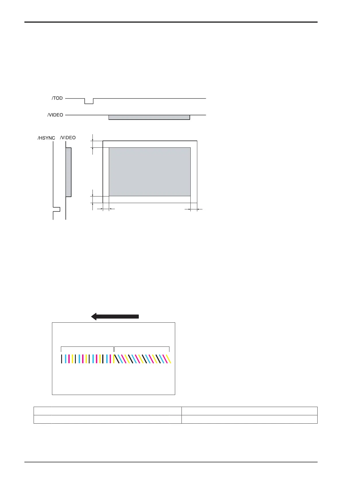
(a)Main scan direction (FD)
• The print start position in the FD direction is determined by the FD print start signal (/HSYNC) that is output from the base board and
the width of the paper.
• The laser emission area is determined by the paper size. However, there is a 4.0 mm (copy) /4.2 mm (PC print) wide void area on both
the both edges of the paper.
(b)Sub scan direction (CD)
• The print start position in the CD direction is determined by the CD print start signal (/TOD) that is output from the base board and the
length of the paper.
• The laser emission area is determined by the paper size. However, there is a 4.0 mm (copy) /4.2 mm (PC print) wide void area on both
the both edges of the paper.
Void width
Void width
Void width
Void width
(5)Color registration control (color shift correction) system
(a)Overview of the registration control
• In a tandem engine, each four different color has an independent image reproduction process. Color shift may occur due to accuracy
differences of parts in the print head unit. The color registration control system automatically detects color shift and correct color shift in
the main and sub scanning directions.
• Color shift is misalignment of the images of three different colors, yellow (Y), magenta (M), and cyan (C), with respect to the image of
black (K).
• The color shift detection sequence proceeds as follows. A pattern is produced on the transfer belt. The IDC sensor reads the
corresponding pattern. The amount of color shift in each of the sub-scanning and main scanning directions is then calculated and
stored in memory.
• The amount of color shift in the sub scanning direction is read from the pattern falling within the sub scanning detection range.
• From data readings, the machine calculates how much the position of each of the different colors should be corrected. Based on the
calculated data, the machine controls each dot during image output, thereby correcting the color shift amount.
[1] Movement direction of the transfer belt [2] Detection area for sub scanning direction
[3] Detection area for main scanning direction - -

 Loading...


