d-Color MF4003/MF3303
P THEORY OF OPERATION > 1. d-Color MF4003/MF3303
P-29
When the number of multi-copies is as specified or over
• The black printing will start when the color mode is complete and the 1st transfer roller /Y/M/C is retracted to be switched to the black
mode. An advantage during retraction of the 1st transfer roller is that chance of the color imaging unit (Y, M, C) being worn as a result
of wasteful rotation can be reduced.
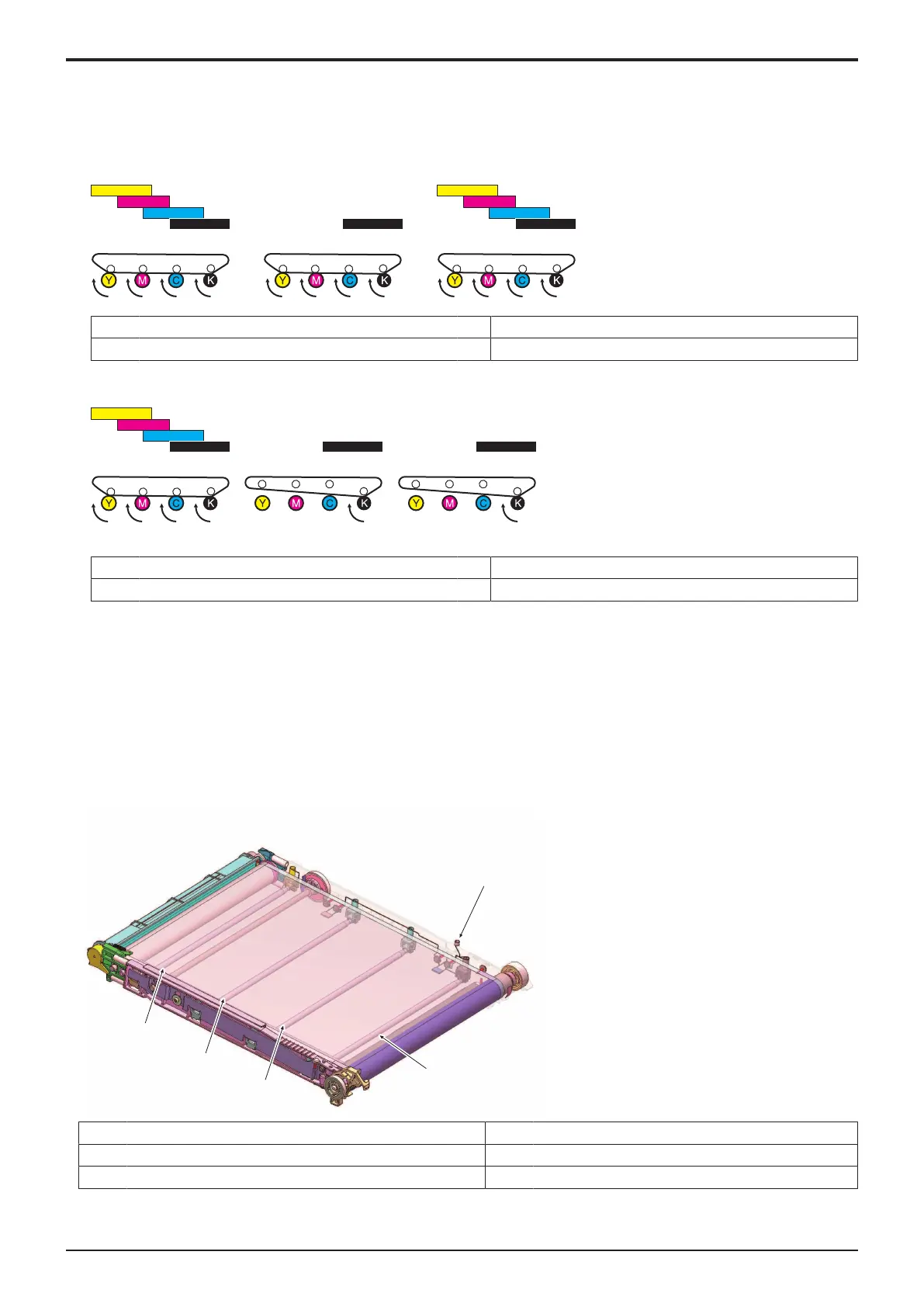
When printing in black with color mode (effecting black printing with the four PC drums rotating)
[1] Color mode [2] Color mode
[3] Color mode - -
Printing after switched to black mode
[1] Color mode [2] Black mode
[3] Black mode - -
(d)ACS mode control change with the Engine FW dip SW
• By changing the engine FW dip SW setting, you can change the pressure control of the 1st transfer rollers in ACS mode.
• When the Engine FW Dip SW “25” is set to “1”, the 1st transfer roller’s default position is changed to the “black mode (retracted
position).” (When the setting is “0”, the default position of the 1st transfer roller/Y, M, C is at the color mode (pressed position).)
• For users who mainly produce black prints, when “1” is selected, the 1st transfer roller/Y, M, C can be at the retracted position more
frequently, which helps to reduce the wearing out of photoconductors caused by unnecessary rotation of color imaging units. The
disadvantage of the setting is that the first copy time becomes longer for color print as the 1st transfer roller/Y, M, C is moved from the
color mode to the black mode. Reduced productivity of the multi-print cycle could result depending on the condition.
(4)1st transfer control
• To transfer the toner image formed on the surface of the photoconductor onto the transfer belt, the transfer current supplied from the high
voltage unit is applied to the 1st transfer roller of each color.
[1] 1st transfer voltage application terminal [2] 1st transfer roller/K
[3] 1st transfer roller/C [4] 1st transfer roller/M
[5] 1st transfer roller/Y -

 Loading...


