d-Color MF4003/MF3303
P THEORY OF OPERATION > 8. FK-517
P-100
Signal which sends alternately a point which rotated 0 point counterclockwise by 180 degrees and a point which rotated 0 point
counterclockwise by 270 degrees
PP Special signal which is sent from a remote station for adjusting an equalizer
TRN Training signal. (Symbol rate and duration are determined in INFOh.)
(a)Control channel signal
• The following signals are used for establishing the control channel or re-synchronization and retrain. (peculiar to half-duplex procedure)
Modulation
method
1200 / 2400 bps QAM modulation (600 ± 0.01
symbols / sec). However, training and synchronous
signals are 1200 bps.
• Calling modem: Carrier (=1200 Hz ± 0.01 % (level = set value))
• Called modem: Carrier (=2400 Hz ± 0.01 % (level = set value-1
dB)) + Guard tone (=1800 Hz ± 0.01 % (level = set value-7 dB))
Sh Signal which sends alternately 0 point and a point which rotated 0 point counterclockwise by 90 degrees (the same as S)
Signal which sends alternately a point which rotated 0 point counterclockwise by 180 degrees and a point which rotated 0
point counterclockwise by 270 degrees (the same as S)
AC Signal which send alternately 0 point and a point which rotated 0 point by 180 degrees
PPh Special signal which is sent from a remote station for adjusting an equalizer (used when the initial of the control channel and
re-synchronization are executed)
ALT Signal which scrambled alternate signals of 0 and 1 (1200 bps)
MPh Binary signal used for exchanging parameters of the
modulation method when data is actually sent and
received by using the main channel (1200 bps)
• Both type 0 and type 1 (type 0+pre-recording coefficient) must
be received.
• When type 0 is received, pre-recording coefficient is considered
to be 0 and never functions.
E “1”, binary of 20 bit, which represents the beginning of user data transmission on the control channel
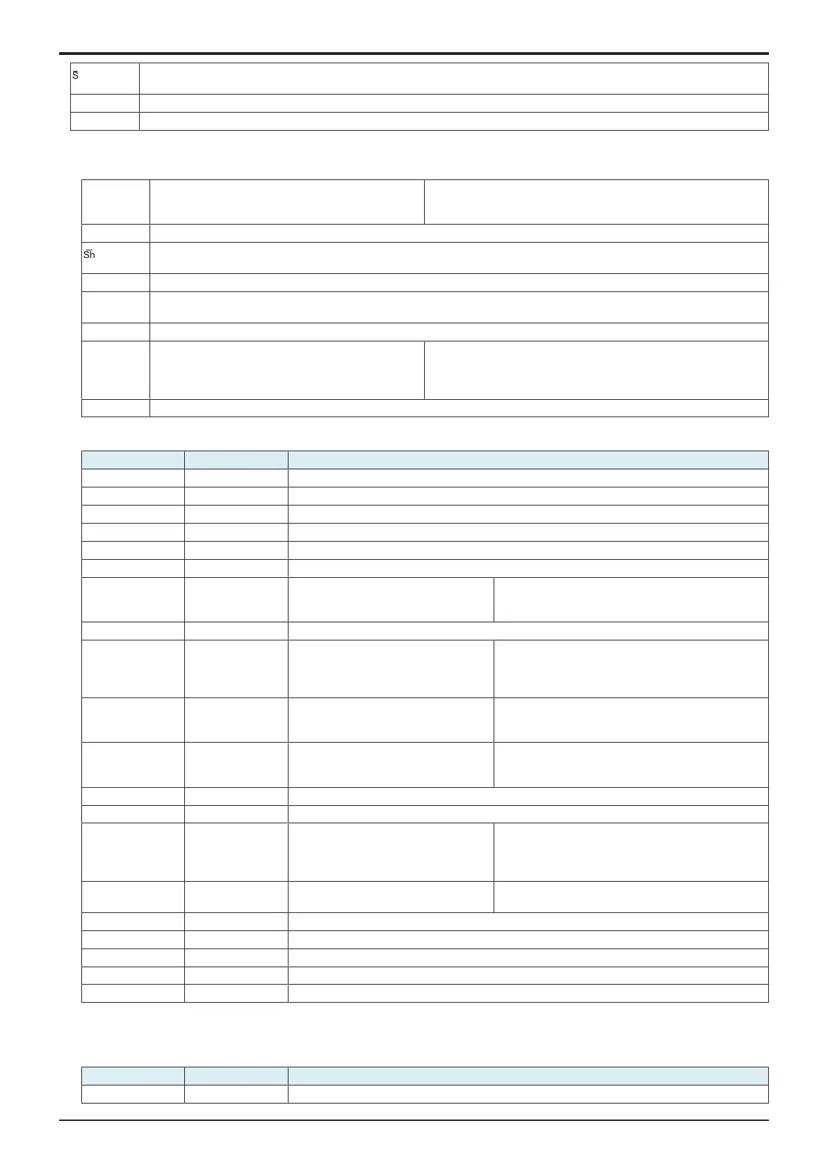
(b)MPh (type 0) bit assignment
Bits (LSB-MSB) Value Meaning
0-16 All bit 1 Bit string for frame synchronization
17 0 Start bit
18 0 MP signal type
19 0 Reserved
20-23 1 to 14 Maximum transmission rate from the calling modem to the called modem (x 2400) *1
24-26 0,0,0 Reserved
27 0/1 Control channel data transmission rate
which is selected by the opposed
transmitter
• 0: 1200 bps
• 1: 2400 bps
28 0 Reserved
29-30 Trellis coding device selection *2 • 00: 16 state
• 10: 32 state
• 01: 64 state
• 11: Reserved
31 0/1 Non-linear encoder parameter selection
for the terminal transmitter of a remote
station *2
• 0: φ=0
• 1: φ=0.3125
32 0/1 Parameter (shaping) selection when the
data rate is determined within each
symbol rate *2
• 0: Minimum
• 1: Expanded
33 0 Reserved
34 0 Start bit
35-49 Communication speed mask (Bit
35=2400 bps ... Bit 46=28.8 kbps, Bit
47=31.2 kbps, Bit 48=33.6 kbps and Bit
49=Reserved)
• 0: Ability of both modems disabled
• 1: Enabled
50 0/1 Use of control channel imbalance data
rate
• 0: No
• 1: Yes
51 0 Start bit
52-67 0 Reserved
68 0 Start bit
69-84 CRC
85-87 0,0,0 Fill Bits
• *1: 13 and 14 are used when the opposed modem supports up to 1664 points.
• *2: Set to 0 on the transmitting modem.
(c)MPh (type 1) bit assignment
Bits (LSB-MSB) Value Meaning
0-16 All bit 1 Bit string for frame synchronization

 Loading...


