P.2.38
SEL-411L Relay Protection Manual Date Code 20151029
Installation
Connection
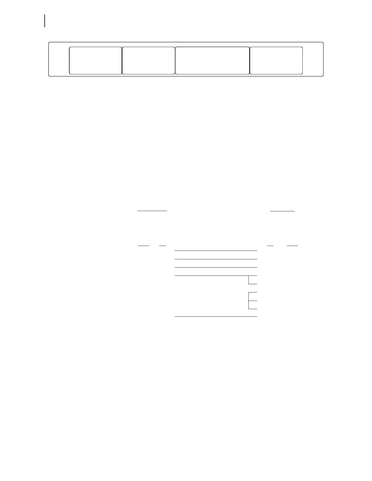
Figure 2.31 Card Layout (Rear View of the Main Board)
Serial Ports
The relay serial communications ports use EIA-232 standard signal levels in a
D-subminiature 9-pin connector. To establish communication between the
relay and a DTE device (a computer terminal, for example) with a
D-subminiature 9-pin connector, use an SEL Cable C234A (see Making an
EIA-232 Serial Port Connection on page P.10.5).
Figure 2.32 shows the configuration of cable SEL-C234A that you can use for
basic ASCII and binary communication with the relay. A properly configured
ASCII terminal, terminal emulation program, or
ACSELERATOR QuickSet
along with the SEL-C234A cable provide communication with the relay in
most cases. See Section 1: Communications Interfaces in the Communications
Manual for a list of hardware interfaces to the relay.
Figure 2.32 Relay to Computer—D-Subminiature 9-Pin Connector
87L Current
Differential Ports
Serial Ports
The relay supports up to two serial ports for current differential protection.
These ports are in the Bay 1 and Bay 2 slots of the relay (see Figure 2.31) and
support the current differential communication interface options listed in
Table 2.9. You can order the relay with either card in either bay position, just
one card in either bay position, or no serial cards at all. Figure 2.33 shows an
example with a G.703 card in Bay 1 (Channel 1) position and an 850nm IEEE
C37.94 fiber card in Bay 2 (Channel 2) position.
Bay 1 Bay 2 Bay 3 Bay 4
87L Serial Communications
Card—Protection
Copper: DB-25 Connector
Fiber: ST Connector
87L Serial Communications
Card—Protection
Copper: DB-25 Connector
Fiber: ST Connector
Serial Communications
Card—Engineering/Time
Port 1, Port 2, Port 3
Copper: DB-9 Connector
IRIG-B: BNC Connector
Network Communications Card—Protection
and/or Engineering
Copper: RJ45 Connector
Fiber: LC Connector
*DTE = Data Terminal Equipment (Computer, Terminal, etc.)
Relay
23
3
5
8
2
5
8
7
RXD TXD
TXD
RXD
GND
GND
CTS
CTS
RTS
DCD
DTR
DSR
1
4
6
SHELL
NO CONNECTION
Pin
Func.
Pin
Func.
Pin
#
Pin
#
9-Pin DTE
Device
*
ORANGE
RED
BLUE
BLACK
SHIELD
9-PIN MALE
“D” SUB CONNECTOR
DB-9-P
9-PIN FEMALE
“D” SUB CONNECTOR
DB-9-S