P.3.75
Date Code 20151029 Protection Manual SEL-411L Relay
Protection Functions
87L Differential Elements
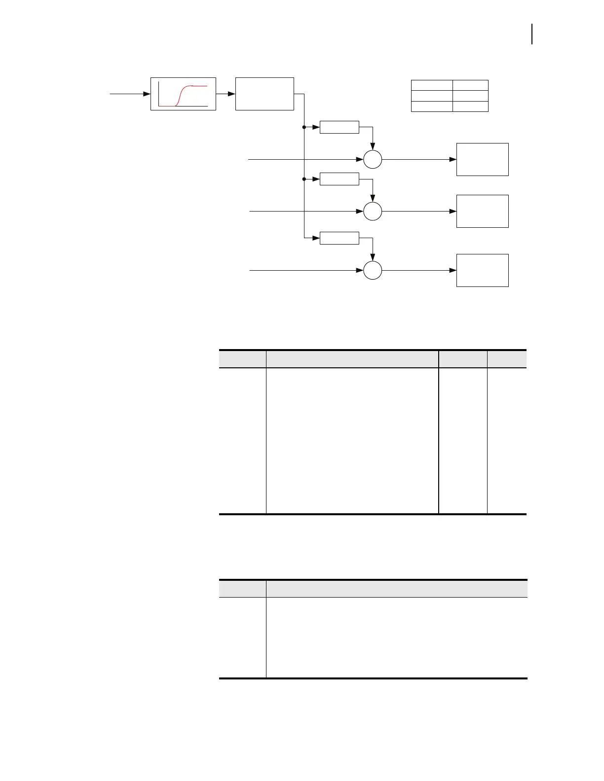
Figure 3.42 Augmenting Restraint Terms for Finite Accuracy of Line Charging Current Compensation at Higher
Frequencies
Table 3.28 shows the settings for the line current compensation function.
Table 3.29 shows the Relay Word bits for the line current compensation
function.
Φ
= A, B, C
Σ
Generalized
Alpha Plane
87L
Φ
Σ
Σ
87I
Φ
DIF
(samples)
High-pass filter
Fundamental frequency restraint with harmonic
boost from the EFD logic, phase
Φ
Fundamental frequency restraint with harmonic
boost from the EFD logic, negative-sequence (3I2)
Fundamental frequency restraint with harmonic
boost from the EFD logic, zero-sequence (3I0)
87kHFP
87kHFQ
87kHFG
87I
Φ
RSTM
87IQRSTM
87IGRSTM
Full-cycle
average of
absolute values
H
f
87kHFP 1.00
87kHFQ 1.00
87kHFG 1.00
Calibration Settings
Generalized
Alpha Plane
87LQ
Generalized
Alpha Plane
87LG
Table 3.28 Line Charging Current Compensation Settings
Setting Description Range Default
E87LCC Enable line charging current compensation Y, N N
87LINEV Relay voltage terminal used by the 87L function Y, Z, OFF Y
87CCLPT Location of voltage transformer used for
charging current compensation (bus, line)
B, L L
87CCB0 Zero-sequence line secondary susceptance,
mSiemens
0.00–100 20
87CCB1 Positive-sequence line secondary susceptance,
mSiemens
0.00–250 60
87CCN Number of line terminals performing charging
current compensation
1–4 2
87TAPCC
a
a
Read-only setting.
CT tap for the calculated charging current 0.1–50 5
Table 3.29 Line Charging Current Compensation Relay Word Bits
Name Description
87CCC Line charging current compensation applied at the local terminal
87CCB Best possible line charging current compensation (compensation performed
using the average of all expected line terminal voltages)
87CCD Line charging current compensation degraded (compensation performed
using the average of some but not all of the expected line terminal voltages)
87CCU Line charging current compensation unavailable