P.3.183
Date Code 20151029 Protection Manual SEL-411L Relay
Protection Functions
Quadrilateral Ground-Distance Elements
The Zone 1 zero-sequence compensation factor (k01) is independent from the
forward and reverse compensation factors (k0 and k0R) that the relay uses for
quadrilateral ground distance protection for the other zones.
When setting E21XG (Quadrilateral Ground Distance Zones) is 1 or more,
there are two selections for setting XGPOL (Quadrilateral Ground Polarizing
Quantity): I2 or IG. When the setting XGPOL is I2, set the first selection in
the setting ORDER (Ground Directional Element Priority) to Q. When the
setting XGPOL is IG, the first selection in the setting ORDER must be Q or V.
The quadrilateral element in the relay includes an option by which the right
resistance blinder can be adapted to load conditions. This adaptive function
applies to the ground quadrilateral elements only; the phase quadrilateral
elements are not affected. The purpose of the adaptive resistance function is to
increase fault resistance coverage, particularly for remote faults. To enable the
adaptive resistance function, set ARESE = Y.
A supervisory condition is applied to force the resistive blinders to be self
polarized under unusual unbalanced loads. The adaptivity of the resistive
blinder is enabled by the setting ARESE, and when the corresponding Relay
Word bit CNR2AG, CNR2BG, CNR2CG, is asserted. When the adaptivity of
the right resistive blinder is disabled it uses self polarization.
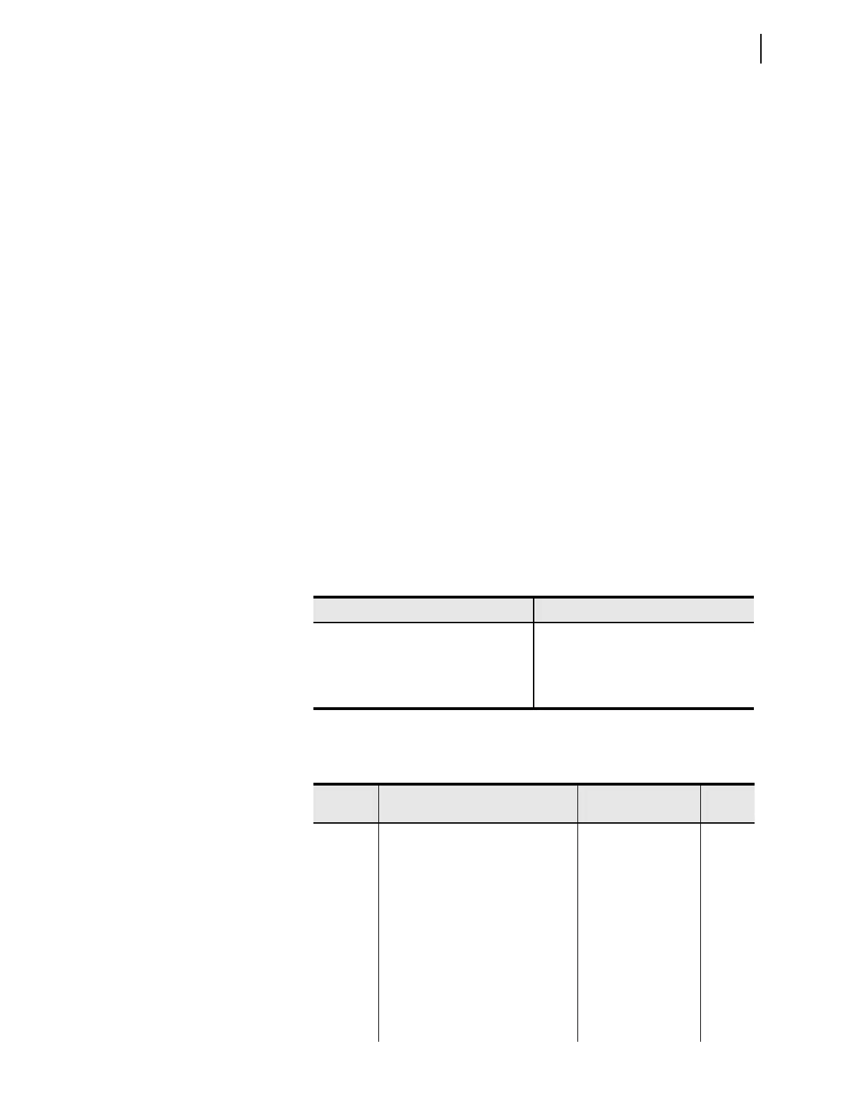
Table 3.92 shows the differences between behavior of the adaptive right
resistance blinder and the existing resistance blinder.
Each quadrilateral ground-distance element is supervised by the Relay Word
bit ENX2nG, where n is the A, B or C phase. This supervisory condition
secures the reactance blinder in the quadrilateral ground-distance element
against unusual unbalanced load conditions.
For more information on the element, see the technical paper Adaptive Phase
and Ground Quadrilateral Distance Elements, available at www.selinc.com.
Table 3.92 Differences Between the Adaptive Right Resistance and the Existing
Resistance Blinder
Existing Resistance Blinder Adaptive Resistance Blinder
The left blinder is the negative of the right-
blinder setting.
The left blinder is the minimum of the
enabled right blinder settings, (min [RG1,
RG2, . . . RGn]).
The right resistance blinder is fixed. The right blinder adapts to the changing
load conditions.
Table 3.93 Quadrilateral Ground-Distance Element Settings
Name Description Range
Default
(5 A)
ARESE Enable adaptive resistive element Y, N N
E21XG Quadrilateral ground distance zones N, 1 to 5 N
XG1 Zone 1 reactance () OFF, (0.25–320)/I
NOM
OFF
RG1 Zone 1 resistance () (0.25–250)/I
NOM
12.48
XG2 Zone 2 reactance () OFF, (0.25–320)/I
NOM
OFF
RG2 Zone 2 resistance () (0.25–250)/I
NOM
18.72
XG3 Zone 3 reactance () OFF, (0.25–320)/I
NOM
OFF
RG3 Zone 3 resistance () (0.25–250)/I
NOM
3.64
XG4 Zone 4 reactance () OFF, (0.25–320)/I
NOM
OFF
RG4 Zone 4 resistance () (0.25–250)/I
NOM
31.20