P.9.12
SEL-411L Relay Protection Manual Date Code 20151029
Monitoring and Metering
Circuit Breaker Monitor
BM1CLSB := BK1CL OR IN205 Breaker Monitor B-phase Close—BK1
(SEL
OGIC Equation)
BM1CLSC := BK1CL OR IN206 Breaker Monitor C-phase Close—BK1
(SEL
OGIC Equation)
Assertion of the Relay Word bit B1ESOAL indicates any one of the
following four conditions:
➤ The electrical operating time for a trip operation exceeds
25 ms (the slow trip alarm setting)
➤ The electrical operating time for a close operation exceeds
65 ms (the slow close setting)
➤ No pole-open logic status change occurred during the time
B1ESTRT plus approximately 100 ms after trip initiation (a trip
time-out condition)
➤ No pole-open logic status change occurred during the time
B1ESCLT plus approximately 100 ms after close initiation (a
close time-out condition)
The relay further checks the circuit breaker by testing whether the circuit
breaker has interrupted or restored current within 100 ms after the end of the
trip or close threshold times. Thus, this additional check serves as the trip
time-out and close time-out condition. This verifies that the circuit breaker
actually closed or opened, and alerts you if maintenance is required on circuit
breaker mechanical linkages.
Pole Scatter
The relay records and compares the operation time of each circuit breaker pole
to detect time deviations between pairs of circuit breaker poles when tripping
and closing all three poles simultaneously on single-pole-capable circuit
breakers. The relay measures the differences in operating times resulting from
auxiliary circuit breaker (52A) contact status changes. The logic compares the
operation time of each individual circuit breaker pole against the time for each
of the other poles. The relay triggers an alarm, B1PSAL, for any time
deviation greater than the preset time threshold settings B1PSTRT and
B1PSCLT for Circuit Breaker 1.
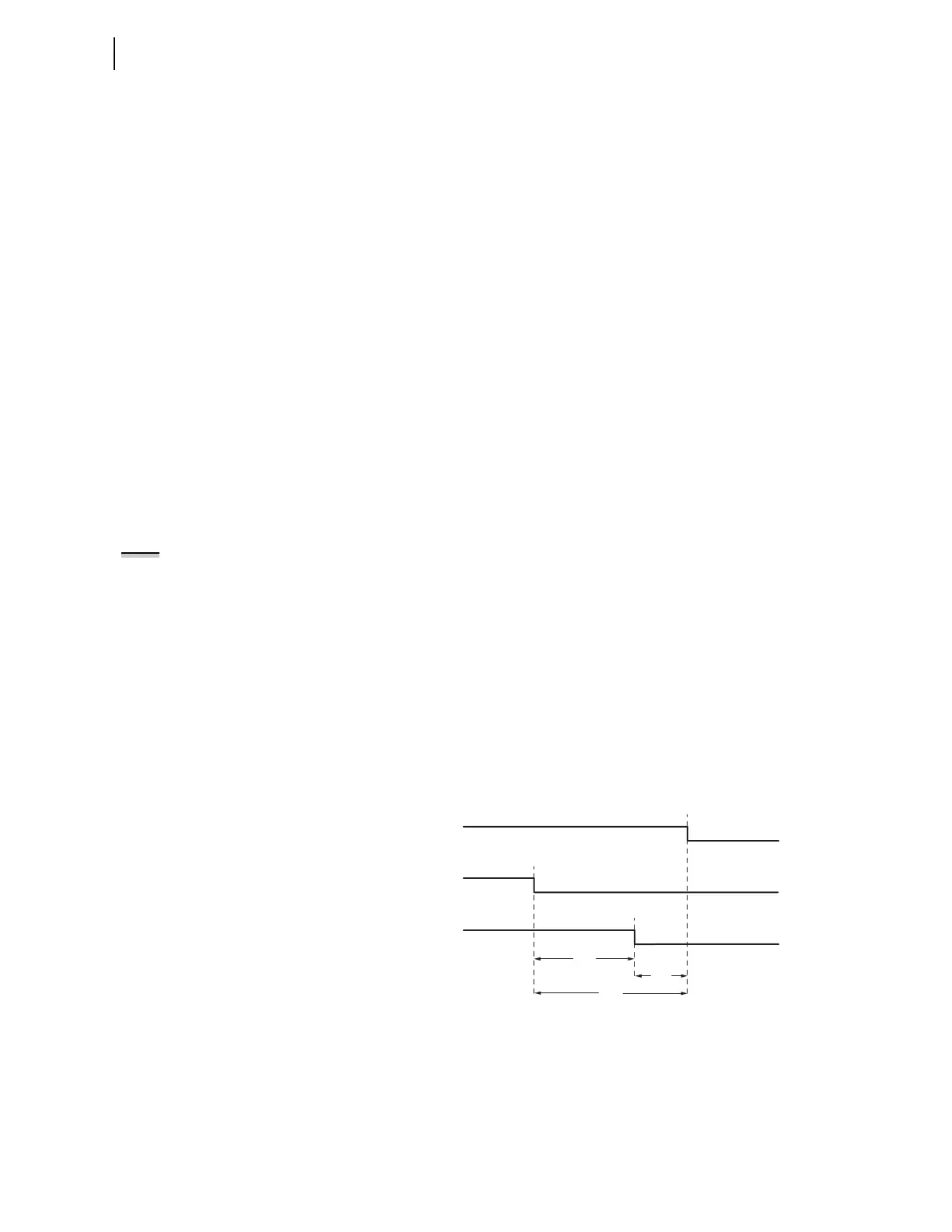
Figure 9.7 shows the operating time for each pole (A, B, and C) of Circuit
Breaker 1. TAB represents the operating time deviation between poles A and
B. TBC is the time between B and C, and TCA is the time between C and A.
Once activated, the pole scatter alarm remains asserted for five seconds.
Figure 9.7 Timing Illustration for Pole Scatter at Trip
NOTE: Pole scatter applies only to
single-pole mechanism circuit
breakers (BK1TYP := 1). These circuit
breakers have an auxiliary circuit
breaker (52A) contact for each phase.
All Poles Closed All Poles Open
Pole B: 52AB1
Pole C: 52AC1
Pole A: 52AA1
TBC
TCA
TAB