P.12.13
Date Code 20151029 Protection Manual SEL-411L Relay
Bay Control
Bay Control Front-Panel Operations
Bay Control Front-Panel Operations
One-Line Diagram and
Labels
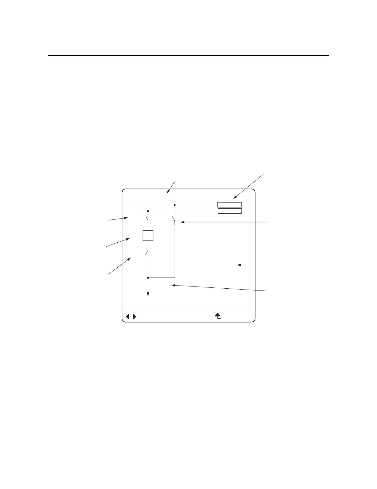
Figure 12.7 is an example of one of the 25 selectable one-line diagrams in the
relay. Select the one-line diagram from the MIMIC settings in the Bay settings
class. If an additional user-selectable bay type has been configured, it is
selected by setting MIMIC to any number in the range of 26–999. The Bay
settings class also has additional Bay class settings for defining labels and
analog quantities. One-line diagrams are comprised of the following:
➤ Bay names
➤ Busbars and busbar labels
➤ Breakers and breaker labels
➤ Disconnect switches and disconnect switch labels
➤ Analog display points
Figure 12.7 Bay Control One-Line Diagram
Front-Panel
Pushbutton
Navigation
Operations in the
One-Line Diagram
Navigation within the one-line diagram requires that the front-panel access
level be at Breaker Access Level or higher and the breaker jumper be installed.
If navigation is attempted when:
➤ the front panel is not at the Breaker Access Level or higher and
passwords are enabled, the relay prompts you to enter the
appropriate passwords.
➤ the breaker jumper is not installed, the Breaker Control
Disabled Please Install the Breaker Jumper
message
briefly appears on the screen.
Use the arrow pushbuttons on the front panel to navigate within the one-line
diagram. When you first select the one-line diagram, none of the apparatus on
the one-line diagram are highlighted. Press a Left Arrow or Right Arrow
pushbutton to enter the one-line diagram and highlight the apparatus in the
Bus Labels
Bay Name
Disconnect
Switch Label
Terminal
Label
Disconnect
Switch Label
Disconnect
Switch Label
Analog
Quantities
Display
Breaker
Label
<BAY 1>
BUS 1
D3
BK1
D1
D2
BUS 2
ESCNAVIG
I:99999 A
V:99999 kV
P:99999 MW
Q:99999 MV
FEEDER1