P.3.56
SEL-411L Relay Protection Manual Date Code 20151029
Protection Functions
87L Differential Elements
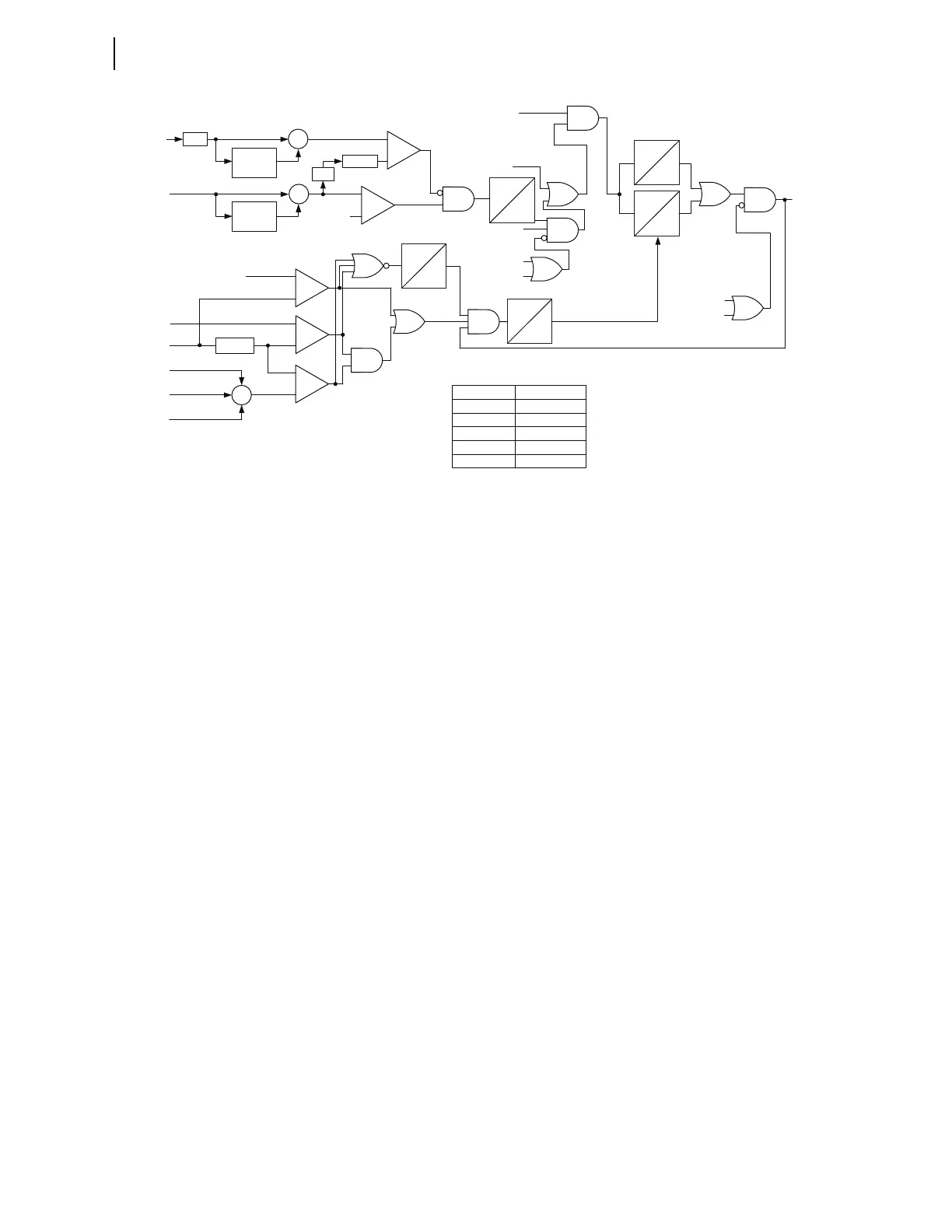
Figure 3.30 External Fault Detection Logic—AC Path and Reset
The “DC path” of the external fault detection algorithm feeds the same timers
as the “AC path” (Figure 3.30). As Figure 3.31 shows, the “DC path” of the
algorithm measures and monitors the level of dc components in the local
currents of the 87L zone. If considerable dc component exists while the
differential current is low, the logic declares an external fault event in
anticipation of the dc component causing CT saturation regardless of the ac
current level.
The logic declares the level of dc component in the W-terminal current high if
the dc component (IWDCM) it measures exceeds the following.
➤ 20% of CT nominal (factory constant, 87PWDC = 0.2 pu)
➤ 30% (factory constant, 87kDC = 0.3) of the measured
fundamental frequency ac component (IWFM)
Upon satisfaction of the previous conditions, and the 87L zone (87CTWL
Relay Word bit asserted) using the W-terminal current, the logic allows the
“DC path” to trigger. The logic performs an identical check for the X-terminal
current of the relay.
If the W-terminal or X-terminal currents show an elevated dc component, and
the differential current magnitude (IDIFM) is less than 50 percent (factory
constant, 87kRD = 0.5) of the restraining current magnitude (IRSTM) for
three power cycles, the “DC path” of the external fault detector will assert.
Supervision with the differential current prevents detector assertion for
internal faults, but the differential current can increase if the CTs actually
saturate. Therefore, the logic includes a seal-in signal to override the low
differential current check (a feedback line in Figure 3.31). Upon seal-in of this
signal, the logic resets if the dc component subsides as compared with the CT
nominal and the ac current component. In addition, the two timers in
Figure 3.30 maintain assertion of the external fault detected bit.
Φ = A, B, C
—
-
+
-
+
-
+
+
-
-
+
87IΦDIF
87IΦRST
87IΦDIFM
87IΦRSTM
87IΦDIFM2
87IΦDIFM4
87IΦDIFM5
87EXFIR
87kEXF
Σ
abs
1-cycle
buffer
1-cycle
buffer
abs
Σ
Σ
87kRD
87DIRTR
From the DC
EFD Logic
87EFDΦ
DC
3/16
cyc
0
3 cyc
0
1 cyc
5 cyc
0
87
EXFMD
0
87
EXFDO
force
dropout
87EFDΦL
Settings
E87L = N
E87CH = N
—
Calibration Settings
87kRD 0.5
87DIRTR 0.75 pu (87L)
87EXFIR 0.2 pu (87L)
87kEXF 0.1
87EXFMD 3 cycles
87EXFD0 60 cycles
87MTR
87DDL
87IFDL
87USAFE