P.3.106
SEL-411L Relay Protection Manual Date Code 20151029
Protection Functions
Current and Voltage Source Selection
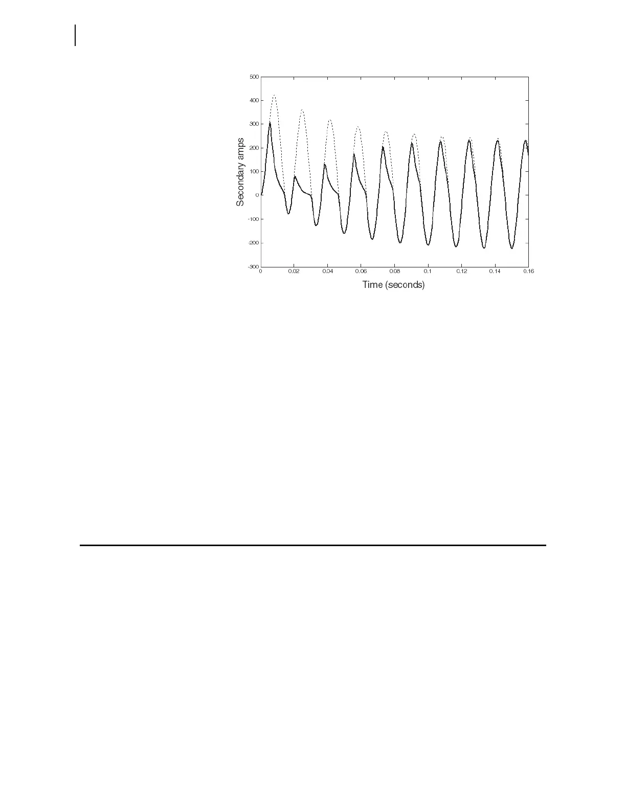
Figure 3.59 Simulation of CT Transient Response on the 600:5 Tap
On the 1200:5 A tap, VS = 800 V. Using Equation 3.40 for the distance
application, we obtain the following:
Three-phase fault:
Equation 3.63
Single-phase-to-ground fault:
Equation 3.64
We can determine from this result that the CT is suitable for both distance and
current differential applications when using the full CT winding.
Current and Voltage Source Selection
The relay has two sets of three-phase current inputs (IW and IX) and two sets
of three-phase voltage inputs (VY and VZ), as shown in Figure 3.60. Currents
IW and IX are also combined internally (COMB = IW + IX) on a per-phase
basis and made available as the line current option for protection, metering,
etc. You can select the current and voltage sources for a wide variety of
applications, using the Global settings in Table 5.14. The relay provides five
default application settings (ESS := N, 1, 2, 3, or 4) that cover common
applications (see Table 3.42). When you set ESS := Y, you can set the current
and voltage sources for other applications (see Table 3.43 and Table 3.44).
ESS settings examples are given later in this subsection.
800
23135 A
240
---------------------
19.303 1+0.5 0.02+
6
------------------------------------------------------------------------------------ 169.62 V=
00
19652 A
240
--------------------- 16.018 1+20.5 0.02+
6
-------------------------------------------------------------------------------------------- 236.89 V=