P.3.21
Date Code 20151029 Protection Manual SEL-411L Relay
Protection Functions
87L Theory of Operation
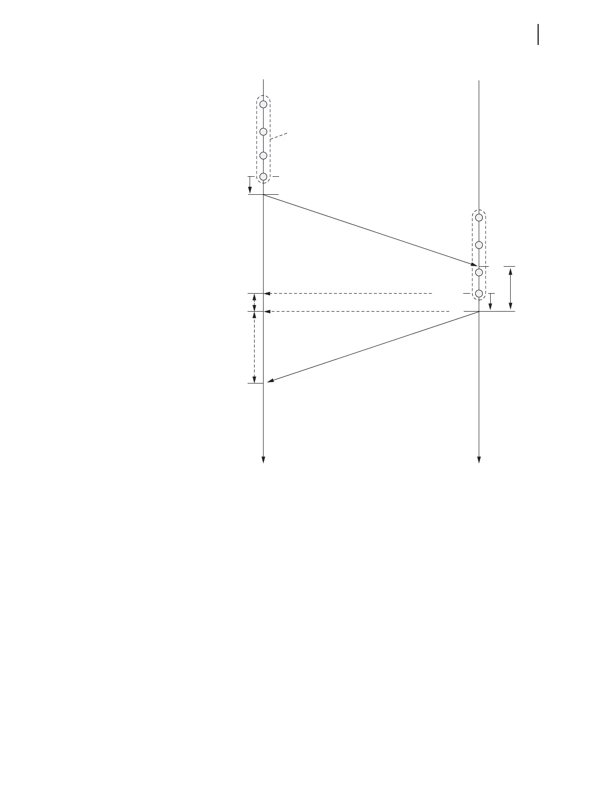
Figure 3.14 Illustration of the Channel-Based Synchronization Method
The packet arrives at Relay 2 after an unknown channel delay time (ranging
from a few milliseconds to tens of milliseconds). Relay 2 uses its own local
clock to capture the packet arrival time t
1
. This clock is asynchronous with the
clock of Relay 1. Time t
1
is necessary to measure the message hold time
(turnaround time) at Relay 2 to facilitate the ping-pong algorithm for
estimation of the channel delay.
Some time later, Relay 2 is ready to send its 87L packet to Relay 1. The
message carries a time stamp of time t
2
in the local time of Relay 2. The hold
time t
H
= t
2
– t
1
is included in the payload of the message. Because of the
constant sampling rate for 87L transmission of the relay, it is possible to pre-
calculate the hold time at some point after capturing t
1
and to place this hold
time conveniently in the packet ahead of the actual transmission. Relay 2
returns the message sequence number, informing Relay 1 that the hold time
Relay 2 returned to Relay 1 was for the message that originated at t
0
.
In its packet, Relay 2 includes a time stamp for the current samples t
DATA
. In
the relay implementation, the packet sequence number and this time stamp are
the same number.
Relay 1 Relay 2
t
D
A
TA
t
0
t
TX
t
1
t
DATA
t
2
t
H
t
3
t
H
, t
DATA
data
t
TX
t
CH
t
TH
t
3
– t
C
H
– t
TX
in Relay 1 time =…
…= t
DATA
in Relay 2 time
Local time at Relay 1
Local time at Relay 2