P.2.22
SEL-411L Relay Protection Manual Date Code 20151029
Installation
Jumpers
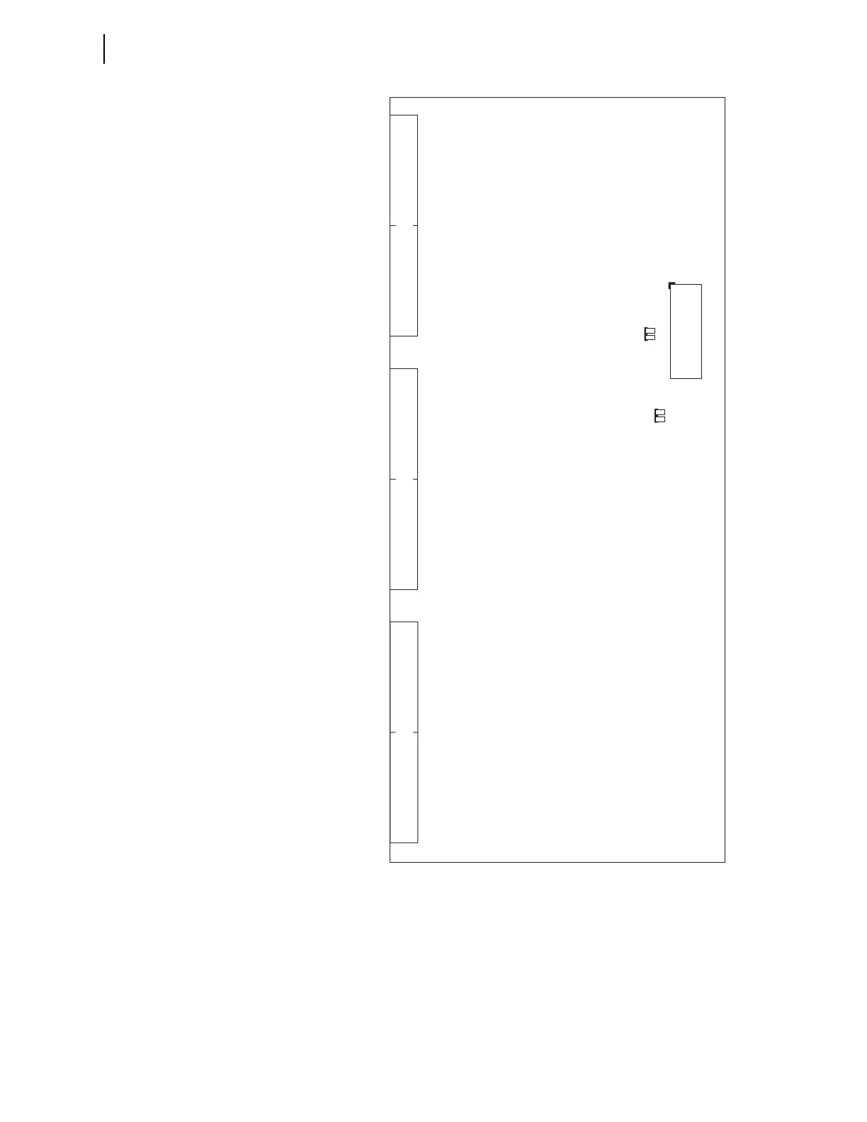
Figure 2.20 Major Jumper and Connector Locations on the INT7 I/O Board
To confirm the positions of your I/O board jumpers, remove the front panel
and visually inspect the jumper placements. Table 2.6 lists the four jumper
positions for I/O interface boards. Refer to Figure 2.17–Figure 2.20 for the
locations of these jumpers.
The I/O board control address has a hundreds-series prefix attached to the
control inputs and control outputs for that particular I/O board chassis slot. A
4U chassis has a 200-addresses slot for inputs IN201, IN202, etc., and outputs
JMP2A
JMP2B
JMP1A
Control Inputs Standard Hybrid Control Outputs Hybrid Control Outputs
JMP1B
Rear of Relay