P.4.61
Date Code 20151029 Protection Manual SEL-411L Relay
Autoreclosing and Synchronism-Check
Synchronism Check
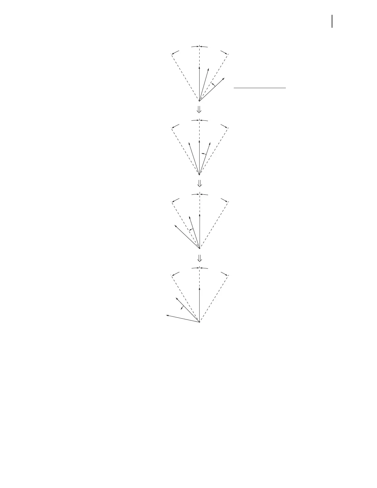
Figure 4.30 “Slip—With Compensation” Synchronism-Check Element Output
Response
Element 25A1BK1 follows V
S1
. With setting 25SFBK1 (maximum slip
frequency) set to other than OFF, the relay calculates V
S1
derived from V
S1
.
Phasor V
S1
leads V
S1
by an angle described by Equation 4.2.
Equation 4.2
From Equation 4.2 note that the angle between V
S1
and V
S1
increases for a
greater slip between V
S1
and V
P
(f
S1
–f
P
), a greater Circuit Breaker BK1 close
time setting TCLSBK1, or both in combination.
For any case [(a), (b), (c), or (d)] in Figure 4.30, the location of V
S1
is the
location of V
S1
a period later (this period is setting TCLSBK1, Circuit
Breaker BK1 Close Time). Consider, for example, issuing a CLOSE
V
P
(a)
(b)
(c)
(d)
V
S1
V'
S1
V
P
V
S1
V
P
V
S1
V
P
V
S1
Response of synchronism-check
element outputs (Relay Word Bits):
25W1BK1 = logical 1
25A1BK1 = logical 1
25W1BK1 = logical 1
25A1BK1 = logical 0
25W1BK1 = logical 0
25A1BK1 = logical 0
25W1BK1 = logical 0 (follows V
S1
)
25A1BK1 = logical 0 (follows V'
S1
)
A
N
G
1
B
K
1
A
N
G
1
B
K
1
A
N
G
1
B
K
1
A
N
G
1
B
K
1
A
N
G
1
B
K
1
A
N
G
1
B
K
1
A
N
G
1
B
K
1
A
N
G
1
B
K
1
V'
S1
V'
S1
V'
S1
Slip (asynchronous systems—not paralleled).
Max slip frequency setting 25SFBK1 other than OFF
angle
f
S1
f
P
– slip cycle
s
60 cyc
s
-----------------•
---------------------------------------------------
360
slip cycle
------------------------ TCLSBK1 (cyc)• • =