P.11.27
Date Code 20151029 Protection Manual SEL-411L Relay
Testing and Troubleshooting
Checking Relay Operation
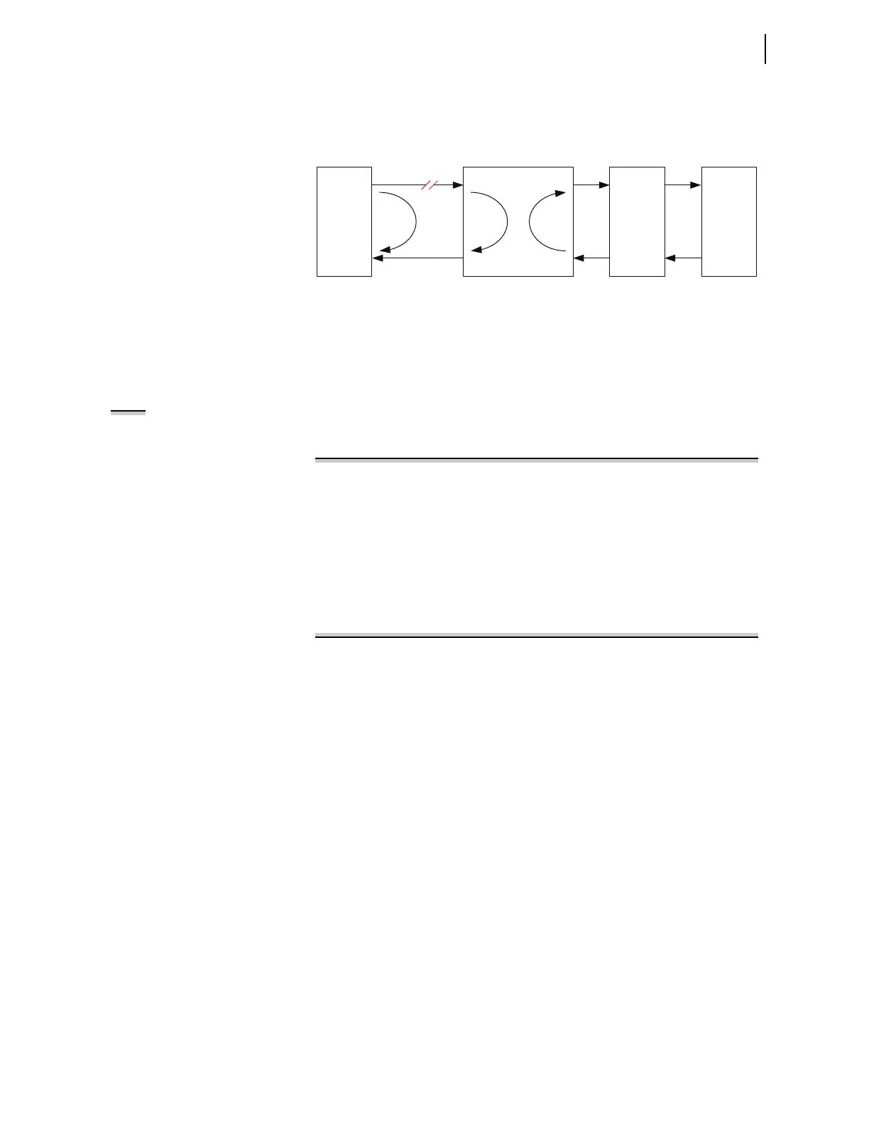
the lost packet loss alarm resets. When the loopback is moved to Terminal 2,
the packet loss alarm returns. A loopback test carried out at Relay 2 with a
loopback at Terminal 3 results in a low packet loss, confirming that the fault
lies between Relay 1 and Mux 1.
Figure 11.11 System Under Loopback Testing
Loopback Test Procedure
Loopback testing can only be carried out if the 87L function is configured to
work with serial channels (E87CH = 2SS, 2SD, 3SS, or 3SM). In addition,
loopback testing is only permitted for channels that are active, meaning the
87L normally transmits on these channels.
NOTE: When the TEST 87L command
is used to carry out a loopback test,
the 87L function will be blocked at all
terminals. However, it is
recommended to isolate the relay
outputs at all terminals to ensure a
false trip does not occur.
Step 1. Use the TEST 87L command to initiate the loopback test.
Select the channel to be tested and the duration for the test.
=>>TEST 87L <Enter>
Entering 87L Test Mode
Select Test: Characteristic or Loopback (C,L) ? L <Enter>
Loopback Test Channel: (1,2) ? 1 <Enter>
Loopback Duration: (1-60 minutes) ? 2 <Enter>
The 87L element inhibited, address checking overwritten,
Testing is enabled
Type "COM 87L" to check the loopback status
Warning!
Ctrl X does not exit test mode
Type "TEST 87L OFF" to exit
=>>
Step 2. Apply a loopback. The following message appears:
Loopback detected on channel <p>
Step 3. Once the loopback is established, use the COM 87L command
to monitor the channel status. If the channel is healthy between
the relay and the loopback, then all channel statistics should be
normal.
Step 4. Use the MET DIF command to view the differential metering.
If there are local currents applied to the relay, then these same
values will appear as the remote terminal currents associated
with the channel under loopback test.
Step 5. Type TEST 87L C to exit Test Mode.
Testing Overcurrent
Elements
Overcurrent elements operate by detecting power system sequence quantities
and asserting when these quantities exceed a preset threshold.
Apply current to the analog current inputs and compare relay operation to the
element pickup settings to test the instantaneous and definite-time overcurrent
elements. Be sure to apply the test current to the proper input set (IW or IX),
according to the Global Current and Voltage Source Selection settings (ESS
and ALINEI, for example) to accept the input. See Current and Voltage
Source Selection on page P.3.106 for more information.
Relay(1)
123
Relay(2)
MUX (1)
Problem
MUX (2)