P.3.282
SEL-411L Relay Protection Manual Date Code 20151029
Protection Functions
87L Active and Required Channel Logic
87L Active and Required Channel Logic
In general, the 87L function of the relay can use a dynamically changing set of
communications channels. This variability results from extra 87L
communications ports you order with a given relay (you order two serial ports,
for example, but need only one for a given application), the needs of the 87L
function according to your configuration, stub bus condition (in which remote
data are not used), and from advanced concepts related to data
synchronization that we explain later in this section.
To better explain relay logic and aid testing, we have made available two
Relay Word bits for signaling usage of a given 87L channel at any given time.
These Relay Word bits describe the active and required status of any given
87L channel.
“Active” refers either to a permanently used channel or to one that can be used
without any delay as a hot stand-by channel or when exiting a stub bus
condition. Therefore, the relay transmits continually on all active channels as
soon as you enable the 87L function and configure it with the associated
settings, as 87L Enable and Blocking Logic explains. The relay also constantly
monitors and alarms on all active channels.
In 87L applications over Ethernet, “channel” refers to Ethernet connectivity to
a given remote relay. All relays work as masters in applications over Ethernet.
Therefore, in the N-terminal application over Ethernet, channels 1 through
N-1 are active.
The 87CHpAC Relay Word bits flag active channels. The variable p refers to
the p-th channel. Consider the variable an abstract with which we can
associate channel measurements, alarms, data synchronization method, status,
and other conditions. All Relay Word bits and analog measurements
associated with the p-th channel contain this enumeration in their names.
Table 3.148 explains the logic driving the 87CHpAC Relay Word bits.
For example, in the 2SS application (a two-terminal application with a single
serial channel) enabled in a relay with two serial ports, the 87PCH setting
dictates which of the two available channels is active. In the 2SD application
(a two-terminal application with redundant serial channels), both channels are
active, regardless of which port the user indicates as primary (i.e., without
considering the 87PCH setting).
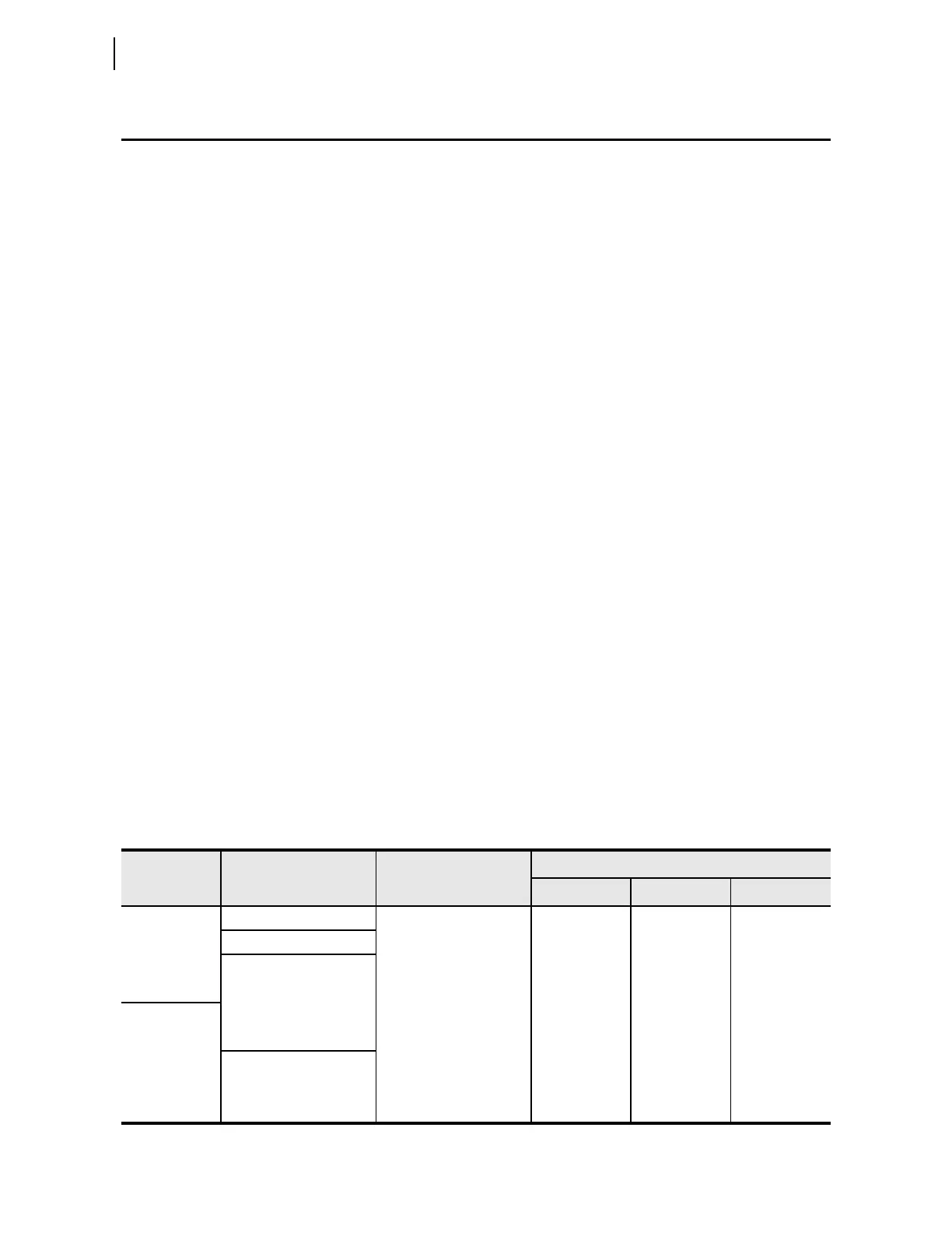
Table 3.148 Active 87L Channels as Determined by the Relay Part Number and the E87CH and 87PCH Settings
Setting
E87CH
Relay Part Number Setting 87PCH
Relay Word Bits
87CH1AC 87CH2AC 87CH3AC
2SS or 3SS
Single 87L port in Bay 1 Hidden and defaulted to 1 1 0 0
Single 87L port in Bay 2 Hidden and defaulted to 2 0 1 0
Two 87L serial ports in
Bays 1 and 2
1100
2010
2SD 1 or 2 1 1 0
3SM Hidden 1 1 0
2E
Ethernet card in Bay 5
Hidden 1 0 0
3E Hidden 1 1 0
4E Hidden 1 1 1