P.3.116
SEL-411L Relay Protection Manual Date Code 20151029
Protection Functions
Current and Voltage Source Selection
Tapped Line
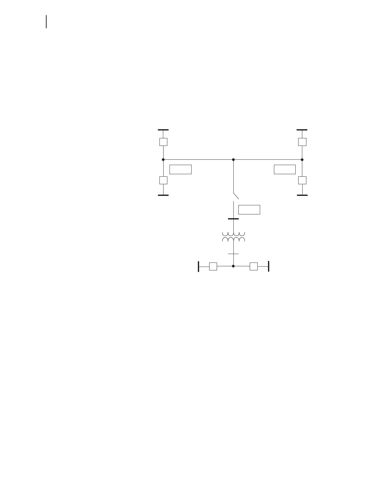
Figure 3.68 illustrates a tapped EHV transmission overhead line. A power
transformer is located at Substation T along the tapped line. A relay is located
at all three EHV terminals (Substations S, R, and T). The relays operate in a
DCB (directional comparison blocking) trip scheme to provide high-speed
clearance for all faults internal to the tapped EHV transmission line.
Set NUMBK (Number of Breakers in Scheme) to 2 so you can program the
autoreclosing function and synchronism-check elements to control both of the
low-side circuit breakers.
Figure 3.68 Tapped EHV Overhead Transmission Line
Figure 3.69 illustrates the tapped overhead transmission line with an MOD
(motor operated disconnect) on the high side of a power transformer and two
circuit breakers on the low side.
Relay
Relay
BK1S
BK1R
BK2S
CB1 CB2
BK2R
Relay
S
R
MOD
(HV)
(LV)
T