P.3.261
Date Code 20151029 Protection Manual SEL-411L Relay
Protection Functions
87L Communication and Timing
87L Communication and Timing
This section describes such basic 87L communications channel options and
configuration parameters as pinout diagrams and cabling options for electrical
interfaces, back-to-back relay connections, relay-to-multiplexer connections,
grounding and shielding, communications clock selection and data sampling
configurations, power budgeting for fiber-based communications, basic
channel addressing to prevent accidental loopback and cross-connections of
relays.
General
In a line current differential application the physical distance between line
terminals necessitates a distributed implementation where the individual
relays are located at each line terminal. A communications network is required
to allow the relays to exchange data. The relay supports data exchange with a
maximum of three remote relays, allowing it to be applied to two-, three-, and
four-terminal lines.
The relay supports two general types of channel for 87L communications:
serial and Ethernet. When serial communications are used, a dedicated
channel is required between each relay in the zone (presuming that all relays
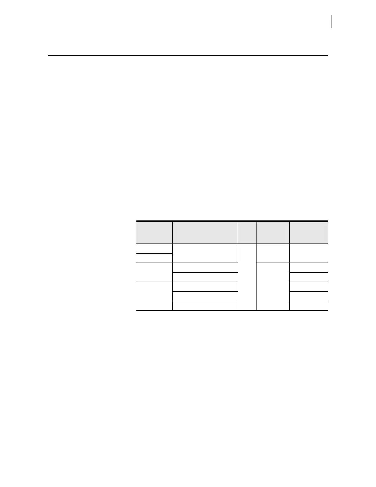
operate as masters). The relay provides the serial interfaces shown in
Table 3.129.
Regarding relay connections, two relays may be connected back-to-back using
either a copper or fiber-optic cable. A copper back-to-back connection can be
useful for bench testing. However, back-to-back connections in the power
system are usually practical only when using a direct-fiber interface because
of the large physical separation of the relays.
More typically, the relay is connected to data circuit terminating equipment
(DCE) such as an interface converter or multiplexer. These devices are
responsible for providing the gain and isolation necessary to exchange data
over long distances. The DCE must have the same interface as the relay and
have matching configurations.
In a relay current differential application, each relay is designated either as a
master or an outstation. A relay is a master if it communicates with all relays
making up the zone and independently arrives at a trip decision. A relay is an
outstation if it does not communicate with all relays within the zone but does
communicate with a master.
Table 3.129 87L Serial Interface Options
Data
Interface
Medium
Data
Rate
Relay
Connection
Maximum
Point-to-Point
Range
EIA-422 Electrical 64 k DB-25 100 ft
CCITT G.703
IEEE C37-94 850 nm multimode fiber ST 2 km
1300 nm single-mode fiber 15 km
Direct Fiber 1300 nm multimode fiber 30 km
1300 nm single-mode fiber 80 km
1550 nm single-mode fiber 120 km