P.3.292
SEL-411L Relay Protection Manual Date Code 20151029
Protection Functions
87L Channel Monitoring and Alarming Logic
Round-Trip Channel
Delay and Step
Change
This monitoring function applies to serial 87L channels only.
The term round-trip channel delay refers to the sum of channel latency in the
receiving and transmitting directions. This is an important attribute of the
channel as it impacts the total trip time of the 87L scheme.
When you use direct point-to-point fiber connections in 87L applications, the
round-trip channel time is constant and should not change. When you use
multiplexed channels, the round-trip time may change when the SONET/SDH
system re-routes data traffic in response to lost fiber connections or failure of a
multiplexer.
In any case, it is beneficial to monitor the round-trip delay and alarm if this
delay exceeds the maximum value for which you applied the 87L scheme, or
when the value is so high that it clearly indicates abnormal operation of the
communications network.
As 87L Theory of Operation explains, the relay measures the round-trip delay
for each of its active channels. This measurement is precise with or without
time sources connected to each relay working over a given 87L channel. The
relay calculates round trip channel delay per the basic equation in 87L Theory
of Operation and averages such raw measurements over a 20 ms (5 packets)
period, and these averaged values become the 87CHpRT analog quantities.
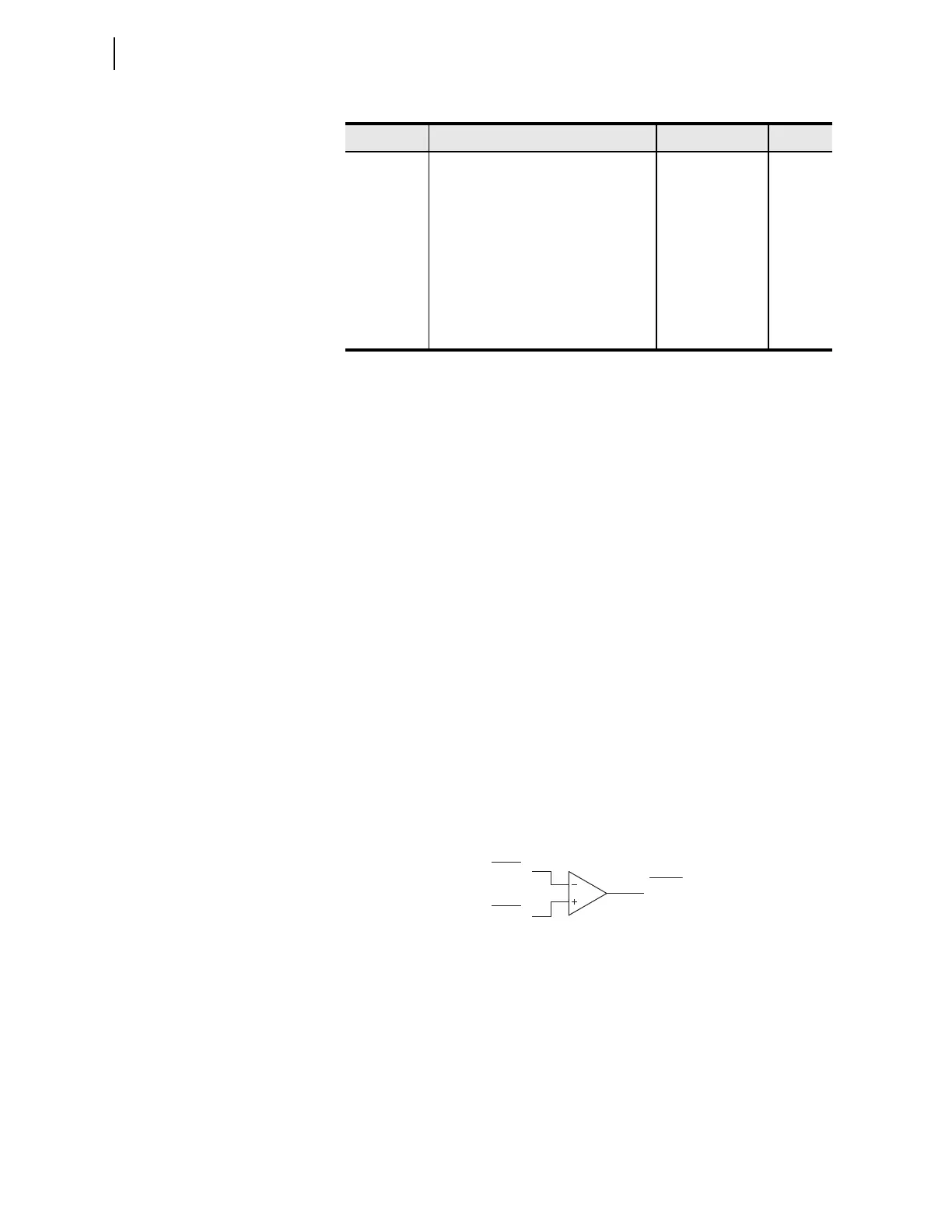
Apply the 87CHpMT setting on a per-channel basis to monitor the value of the
round-trip delay, as Figure 3.200 illustrates. The 87CHpT Relay Word bit
signals an alarm.
Figure 3.200 Maximum Round-Trip Delay Alarm Logic
A step change in the round-trip delay is another important channel attribute.
The relay monitors for the step change in the round-trip delay as a part of its
channel-monitoring function set. The relay also uses this information as a part
of some of the time fallback modes when you apply external time-based
synchronization. In this context, the step change in the round-trip delay is a
positive proof of channel switching and, therefore, a possible change in
channel symmetry (see 87L Time Fallback Logic for more details).
As Figure 3.201 shows, the relay defines the step change in the round-trip
delay as the difference between the round-trip delay just prior and just after a
channel interruption. This takes advantage of the fact that the communications
87CH1MA Maximum channel asymmetry threshold
for the 87L Channel 1 (ms)
OFF, 0.2–10 OFF
87CH2MA Maximum channel asymmetry threshold
for the 87L Channel 2 (ms)
OFF, 0.2–10 OFF
87CH1PC Lost packet alarm threshold for the 87L
Channel 1
OFF, 1–2500 OFF
87CH2PC Lost packet alarm threshold for the 87L
Channel 2
OFF, 1–2500 OFF
87CH3PC Lost packet alarm threshold for the 87L
Channel 3 (Ethernet only)
OFF, 1–2500 OFF
Table 3.154 87L Channel Alarm Settings (Sheet 2 of 2)
Setting Description Range Default
Setting
Analog
Relay
Word Bit
87CHpMT
87CHpRT
87CHpT