P.2.4
SEL-411L Relay Protection Manual Date Code 20151029
Installation
Shared Configuration Attributes
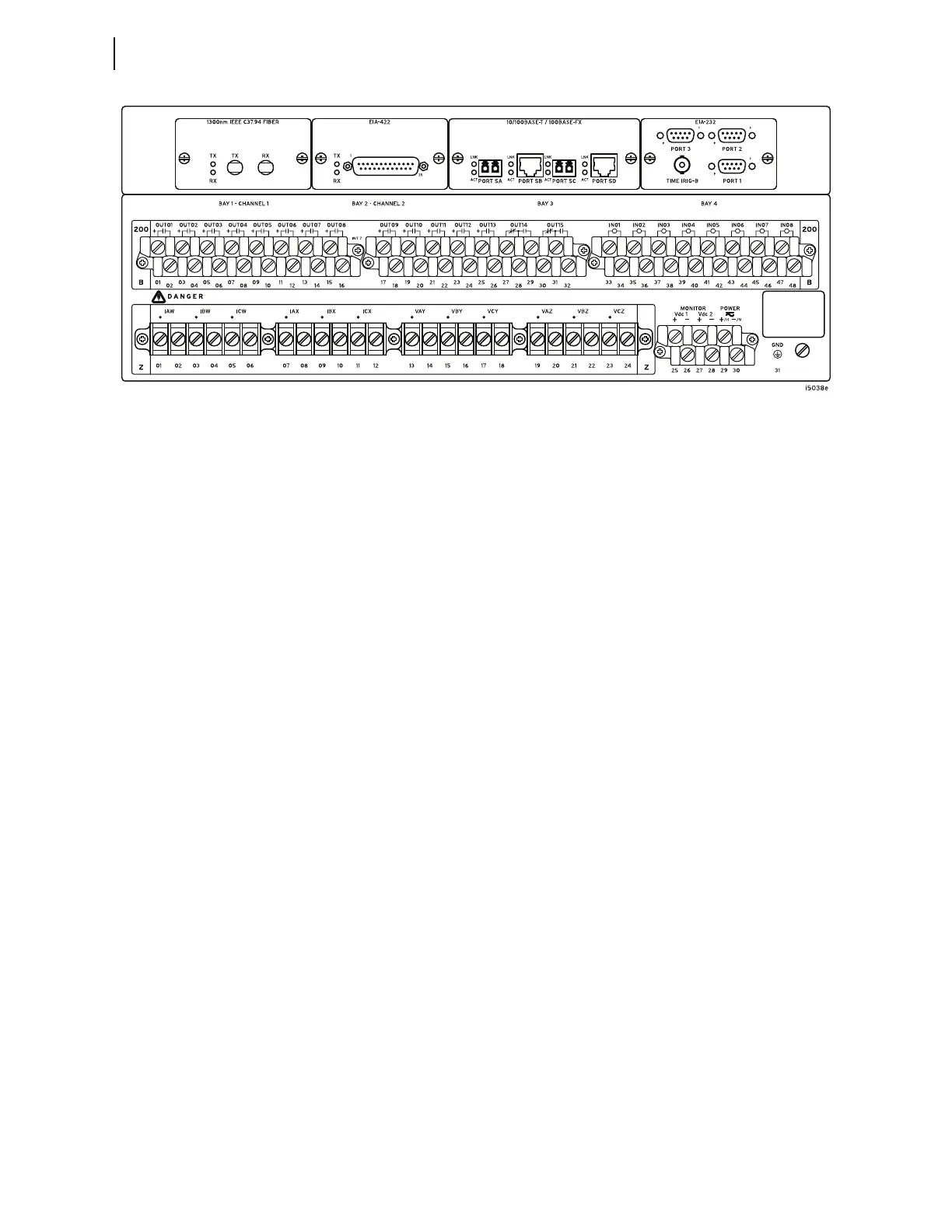
(In a vertical-mount relay, the right rear side is at the top.)
Figure 2.2 Rear 4U Template, Fixed Terminal Block Analog Inputs
Secondary Circuits
The relay is a very low burden load on the CT secondaries and PT
secondaries. For both the CT and PT inputs, the frequency range is 40–65 Hz.
The relay accepts two sets of three-phase currents from power system CT
inputs:
➤ IAW, IBW, and ICW
➤ IAX, IBX, and ICX
For 5 A relays, the rated nominal input current, I
NOM
, is 5 A. For 1 A relays,
the rated nominal input current, I
NOM
, is 1 A.
Input current for both relay types can range to 20 • I
NOM
.
See AC Current Input (Secondary Circuit) on page P.1.13 for complete CT
input specifications.
The relay also accepts two sets of three-phase, four-wire (wye) potentials from
power system PT or CCVT (coupling-capacitor voltage transformer)
secondaries:
➤ VAY, VBY, and VCY
➤ VAZ, VBZ, and VCZ
The nominal line-to-neutral input voltage for the PT inputs is 67 volts with a
range of 0–300 volts. See AC Voltage Inputs on page P.1.13 for complete PT
input specifications.
Some applications do not use all three phases of a source; for example, voltage
synchronization sources can be single phase. See Section 1: Introduction and
Specifications for examples of connections to the potential inputs.
See Secondary Circuit Connections for information on connecting power
system secondary circuits to these inputs.