P.3.15
Date Code 20151029 Protection Manual SEL-411L Relay
Protection Functions
87L Theory of Operation
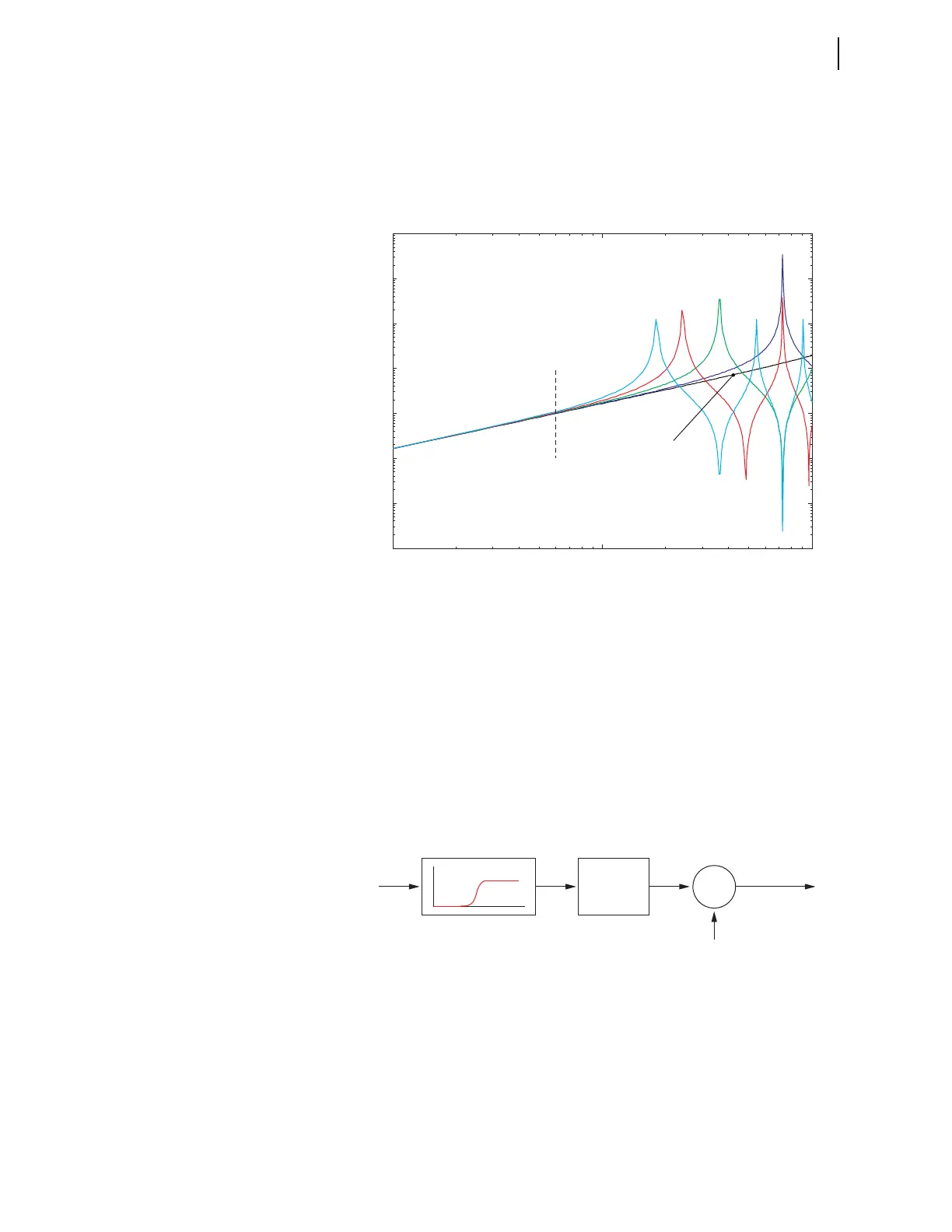
parameter nature of the actual line and the lumped parameter model in use for
charging current compensation is irrelevant for frequencies greater than a few
hundred Hz, because the relay measurement algorithms filter out these
frequency components. However, at frequencies less than a few hundred Hz,
the over- or under-compensated charging current components can potentially
decrease the effect of compensation.
Figure 3.8 Admittance of a Sample Transmission Line as a Function of
Frequency and Line Length in Per-Unit of the Value at 60 Hz Differences
Between the Distributed Line and Its Lumped Parameter Model Can Lead to
Under- or Over-Compensation of the Charging Current
The relay solves this problem by applying a high-pass filter to the differential
current and using the rms measurement at its output to increase the natural
restraining term for the phase currents prior to applying the generalized Alpha
Plane (see Figure 3.9). In this way, the relay compensates for the bulk of the
charging current by decreasing the differential current. The relay deals with
the remainder resulting from the mismatch between the line model and the
actual line by boosting the restraint term proportionally to the standing high
frequency components in the differential signal. Note that decreasing the
differential term and increasing the restraint term brings the operating point of
the generalized Alpha Plane closer to the ideal blocking point.
Figure 3.9 The Under- or Over-Compensated High-Frequency Components of
the Charging Current Are Taken Care of by Boosting the Fundamental
Frequency Restraining Term
The actual relay implementation of the line charging current algorithm
requires knowledge of the location of potential sources. With bus-side voltage
transformers (VTs), the relay suspends compensation at a given terminal if the
breaker opens because the bus voltage no longer represents the line voltage.
Also, a loss-of-potential condition inhibits compensation. When potential
10
1
10
2
10
3
10
-3
10
-2
10
-1
10
0
10
1
10
2
10
3
10
4
Frequency, Hz
Admittance - mag, pu
60 Hz
400 km
300 km
200 km
100 km
Lumped parameter
model
i
DIF
k*RMS
Σ
Fundamental
Frequency
Restraint
Effective
Restraint
f
H