P.2.11
Date Code 20151029 Protection Manual SEL-411L Relay
Installation
Plug-In Boards
Plug-In Boards
The relay is available in many input/output configuration options. The relay
base model is a 4U chassis with one I/O, board (there are no I/O on the main
board) and screw terminal connector connections (see Figure 2.2). Other
ordering options include versions of the relay in larger enclosures (5U and 6U)
with all, partial, or no extra I/O boards installed.
NOTE: Ordering the 5U and 6U
relays with partial I/O allows for future
system expansion and future use of
additional relay features.
Plug-in communications cards are also available for line current differential
protection as well as communication. The optional Ethernet card is available
at the time of purchase as a factory-installed option or as a factory-installed
conversion to an existing relay.
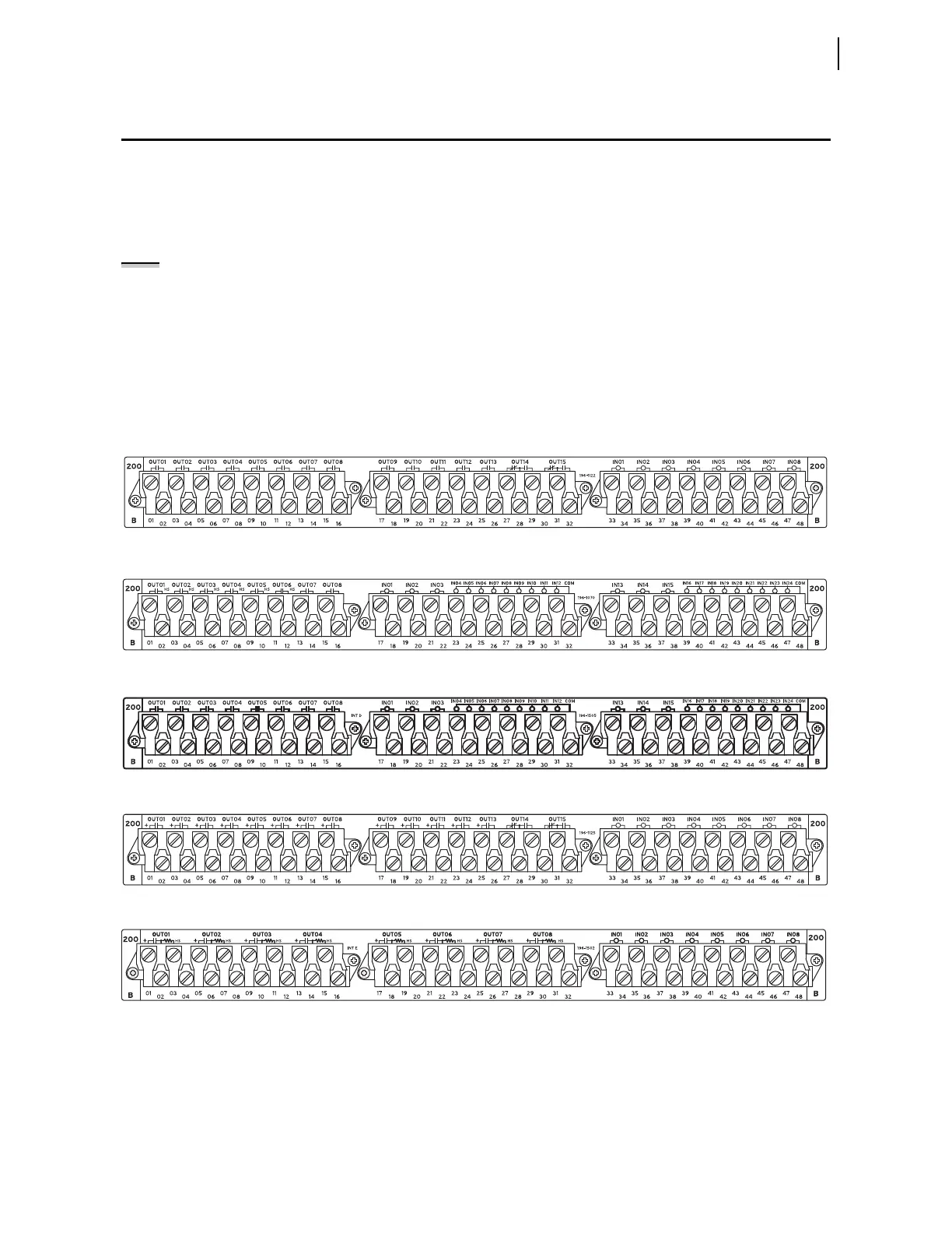
I/O Interface Boards
You can choose among five input/output interface boards for the I/O slots of
the 4U, 5U, and 6U chassis. The I/O interface boards are INT2, INT7, INTC,
INTD, and INTE. Figure 2.9–Figure 2.13 show the rear screw terminal
connectors associated with these interface boards.
Figure 2.9 INT2 I/O Interface Board
Figure 2.10 INTC I/O Interface Board (High Speed)
Figure 2.11 INTD I/O Interface Board (Standard)
Figure 2.12 INT7 I/O Interface Board
Figure 2.13 INTE I/O Interface Board
The I/O interface boards carry jumpers that identify the board location (see
Jumpers).