P.7.27
Date Code 20151029 Protection Manual SEL-411L Relay
Front-Panel Operations
Front-Panel Menus and Screens
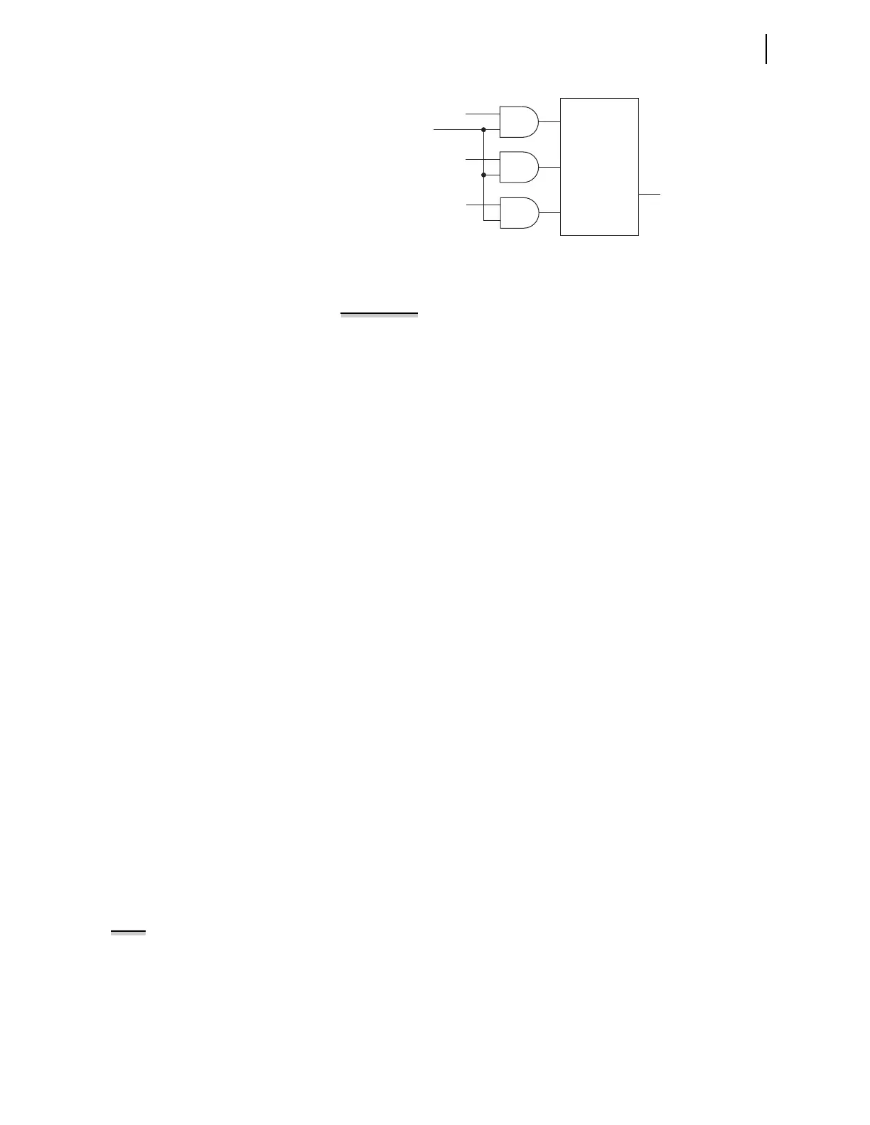
Figure 7.31 Local Bit Supervision Logic
EXAMPLE 7.4 Enabling Local Bit Control
This application example demonstrates a method to create one of the
control points in the LOCAL CONTROL screens of Figure 7.30 to
control the interlock on a power bus tie circuit breaker. Perform the
following actions to create a local control bit:
➤ Eliminate previous usage of the local bit and condition the
state of the local bit
➤ Set the local bit
➤ Assign the local bit to a relay output
If you are using a previously used local bit, delete all references to the
local bit from the SEL
OGIC control equations already programmed in
the relay. A good safety practice would be to disconnect any relay
output that was programmed to that local bit.
To change the local bit state, select the bit and set it to the state you
want. In addition, you can delete the local bit, which changes the state
of this local bit to logical 0 when you save the settings. To delete, use
the front-panel settings. When using a communications port and
terminal, use the text-edit mode line setting editing commands at the
Local Bits and Aliases prompt to go to the line that lists Local Bit 9.
(See Text-Edit Mode Line Editing on page P.10.18 for information on
text-edit mode line editing.) To delete Local Bit 9, type DELETE <Enter>
after the line that displays Local Bit 9 information. For example, if a
previously programmed Local Bit 9 appears in the SET F line
numbered listings on Line 1, then typing DELETE <Enter> at Line 1
deletes Local Bit 9.
Next, set the local bit. In the front-panel settings (SET F), enter the
following:
1: LB09,“Bus Tie Interlock”,“Closed (OK to TIE)”,“Open (No TIE)”,N
This sets Local Bit 9 to “Bus Tie Interlock” with the set state as
“Closed (OK to TIE)” and the clear state as “Open (No TIE).”
Assign the local bit to a relay output. In the Output settings (SET O),
set the SEL
OGIC control equation, OUT201, to respond to Local Bit 9.
OUT201 := LB09
Use the appropriate interface hardware to connect the circuit breaker
interlock to OUT201.
OUTPUT TESTING
You can check for proper operation of the relay control outputs by using the
OUTPUT TESTING submenu of the LOCAL CONTROL menu. A menu screen
similar to Figure 7.32 displays a list of the control outputs available in your
relay configuration. For more information on output testing, see Control
Output on page P.10.21.
Logic to Set,
Clear, or
Pulse LBn
LBn
Set
Clear
Pulse
LB_SPn*
*SEL
OGIC
Control Equation
NOTE: The circuit breaker control
enable jumper BREAKER must be
installed to perform output testing
(see Main Board Jumpers on
page P.2.14).