P.10.2
SEL-411L Relay Protection Manual Date Code 20151029
Basic Relay Operations
Inspecting a New Relay
Cleaning
Perform the following steps and use care when cleaning the relay.
Step 1. Use a mild soap or detergent solution and a damp cloth to clean
the relay chassis.
Be careful cleaning the front and rear panels because a
permanent plastic sheet covers each panel; do not use abrasive
materials, polishing compounds, or harsh chemical solvents
(such as xylene or acetone) on any relay surface.
Step 2. Allow the relay to air dry, or wipe dry with a soft dry cloth.
Verify Relay
Configuration
When you first inspect the relay, confirm that the relay power supply voltage
and nominal ac signal magnitudes are appropriate for your application.
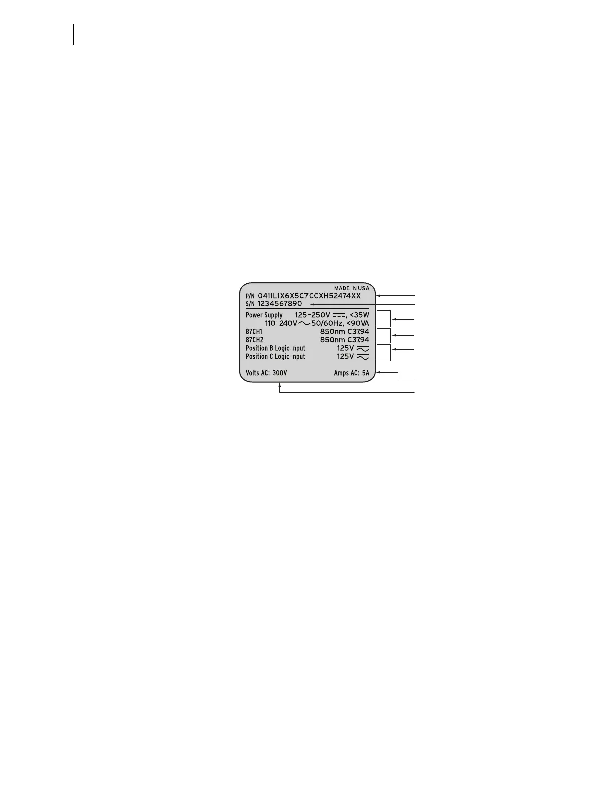
Examine the serial number label on the relay rear panel; Figure 10.1 shows a
sample rear-panel serial number label.
Figure 10.1 Serial Number Label
Figure 10.1 shows a serial number label for a relay. This example serial
number label is for a 5 A-per-phase secondary current transformer input relay.
For information on CT and PT inputs, see Secondary Circuits on page P.2.4.
The serial number label does not list power system phase rotation and
frequency ratings, because you can use relay settings to configure these
parameters. The factory defaults are ABC phase rotation and 60 Hz nominal
frequency.
The power supply specification in Figure 10.1 indicates that this relay is
equipped with a power supply that accepts a nominal 125–250 Vdc input. This
power supply also accepts a 110–240 Vac input. The other option is a 48–125 Vdc
power supply. The 48–125 Vdc power supply also accepts a 110–120 Vac
input. Refer to the serial number label affixed to the back of your relay to
determine the power supply voltage you should apply to the relay power
supply input terminals. As this label indicates, the voltage source should be
capable of providing at least 35 W or 90 VA. See Power Supply on page P.1.13
for more information on power supply specifications.
Logic Input Ratings
The serial number label in Figure 10.1 only lists control input voltages for I/O
Interface Boards that have 24 optoisolated inputs, which is determined at
ordering time. In the sample shown, only Slot B contains an INTC and INTD
I/O Interface board, so only one input rating appears.
Part Number
Serial Number
Power Supply Input Specifications
Secondary Voltage Input
Secondary Current Input
I/O Interface Board(s)
Logic Input Rating
(See Logic Input Ratings, below)
87L Channel Interface