P.3.333
Date Code 20151029 Protection Manual SEL-411L Relay
Protection Functions
Protection Application Examples
Use the data from Table 3.168 to calculate the secondary impedances listed in
Table 3.169.
Application Summary
This application is for a single circuit breaker with three-pole tripping and the
following protection functions:
➤ Line current differential protection with line-charging current
compensation
➤ Master/outstation operation
➤ Overcurrent backup protection
Relay settings that this example does not mention do not apply to this
application example.
Line impedance
Z1L1 = Z1L2 = Z1L3
Z0L1 = Z0L2 = Z0L3
B1L1 = B1L2 = B1L3
B0L1 = B0L2 = B0L3
0.55 / mile 86.15° primary
2.07 / mile 73.29° primary
7.79 S / mile primary
4.80 S / mile primary
Transformer
MVA
Leakage Reactance
Connection
Ratio
225
8%
YDAB
345/69 kV
Source S Impedance
Z1S = Z0S 24 87° primary
Source R Impedance
Z1R = Z0R 18 87° primary
Source T Impedance
Z1T = Z0T 20 87° primary
Maximum line current 1000 A 10°
PTR (Potential transformer ratio) 345 kV: 115 V = 3000
At terminals S and R
Current transformer ratio
CT class (both)
Burden (both)
At terminal T
Current transformer ratio
CT class
Burden
S = 1000:5 = 200, R = 800:5 = 160
C800
1.5
2000:1 = 2000 (Phase)
100:1= 100 (Neutral)
C400
2.5
Phase rotation ABC
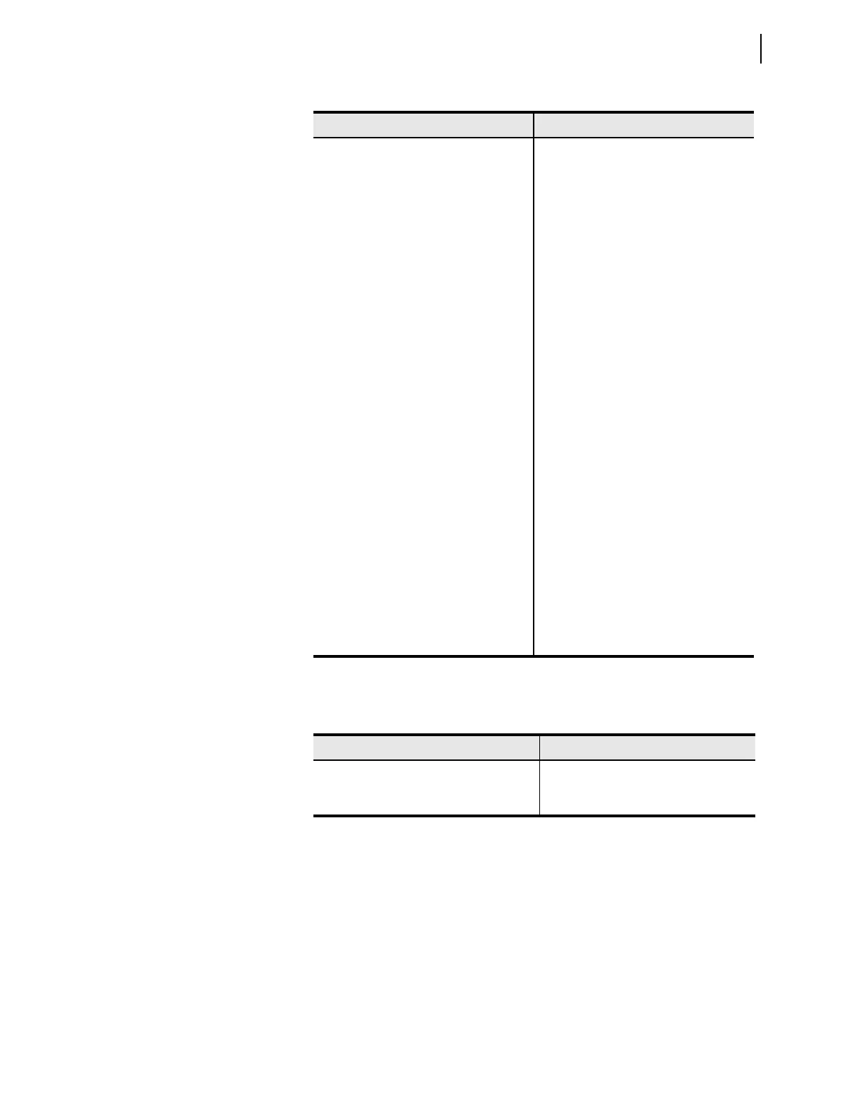
Table 3.169 Secondary Impedances
Parameter Value
Line Susceptance (Terminal S = Terminal R)
B1L (L1 + L2 + L3)
B0L (L1 + L2 + L3)
26.9 mS
16.5 mS
Table 3.168 System Data—345 kV Overhead Transmission Line (Sheet 2 of 2)
Parameter Value