P.12.9
Date Code 20151029 Protection Manual SEL-411L Relay
Bay Control
Disconnect Logic
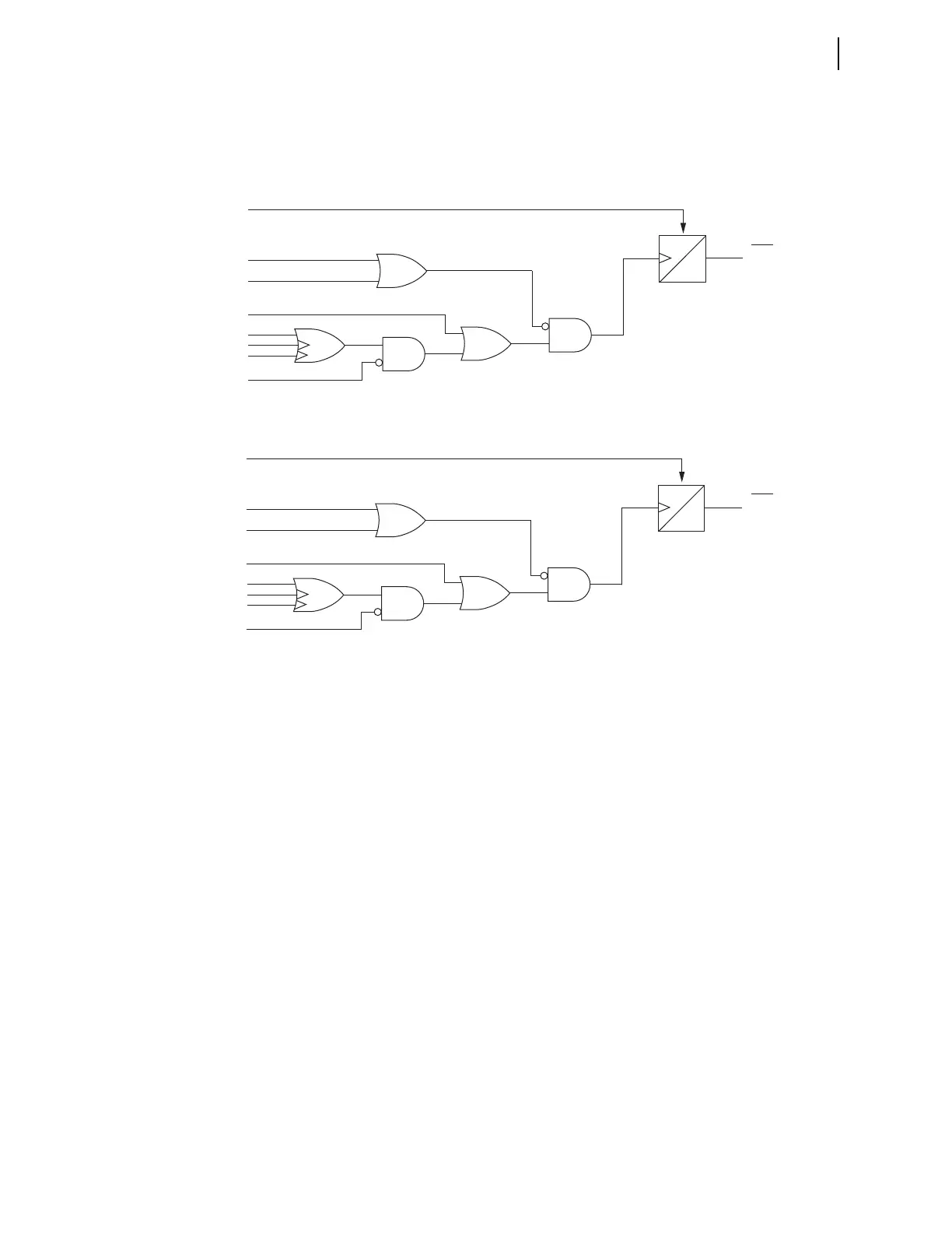
Close and Open Immobility Timer Logic
Introduction
The close and open immobility timer logic detects when a disconnect
operation failed to initiate.
Figure 12.4 Close Immobility Timer Logic
Figure 12.5 Open Immobility Timer Logic
Disconnect Switch Close and Open Immobility Timer Logic Inputs
LOCAL
The LOCAL Relay Word bit supervises local disconnect control and is based
on the LOCAL SEL
OGIC control equation in the Bay settings class.
Disconnect switch operations from the front panel are possible only when the
LOCAL Relay Word bit is asserted, in other words, the LOCAL Relay Word
bit prevents control from the HMI without proper supervision.
89CBLm, 89OBLm
The 89CLBLm and 89OPBLm SELOGIC control equations provide an
alternative customizable method for blocking the initiation of a disconnect
switch OPEN or CLOSE command, respectively.
89CIRm, 89OIRm
The 89CITm and 89OIRm SELOGIC control equations provide the flexibility
to customize resetting the Close and Open Immobility Timers. By default,
89CIRm is set to NOT 89OPNm, and 89OIR is set to NOT 89CLm.
89CLm, 89OPNm
The 89CLm and 89OPNm Relay Word bits report the state of the disconnect
switches. If the disconnect switch is closed, Relay Word bit 89CLm is
asserted. If the disconnect switch is open, Relay Word bit 89OPNm is
asserted. See Figure 12.3 for a description of these inputs.
Close Immobility Timer
89CITm
60
CYC
*89CIRm
(default setting:
NOT 89OPNm)
Relay
Word
Bits
* SEL
OGIC
control equation
** This SEL
OGIC
control equation processed
at 1/8 cycle
89CIMm
(Reset)
*89CBLm
89OPEm
89CCMm
89CCm (ASCII)
**89CCNm (k – 1/8 cyc.)
**89CCNm (k)
*LOCAL
3
4
2
1
1
Open Immobility Timer
89OITm
60
CYC
*89OIRm
(default setting:
NOT 89CLm)
Relay
Word
Bits
89OIMm
(Reset)
*89OBLm
89CLSm
89OCMm
89OCm (ASCII)
**89OCNm (k – 1/8 cyc.)
**89OCNm (k)
LOCAL
3
4
2
1
1
* SEL
OGIC control equation
** This SEL
OGIC control equation processed
at 1/8 cycle