P.2.17
Date Code 20151029 Protection Manual SEL-411L Relay
Installation
Jumpers
Serial Port Jumpers
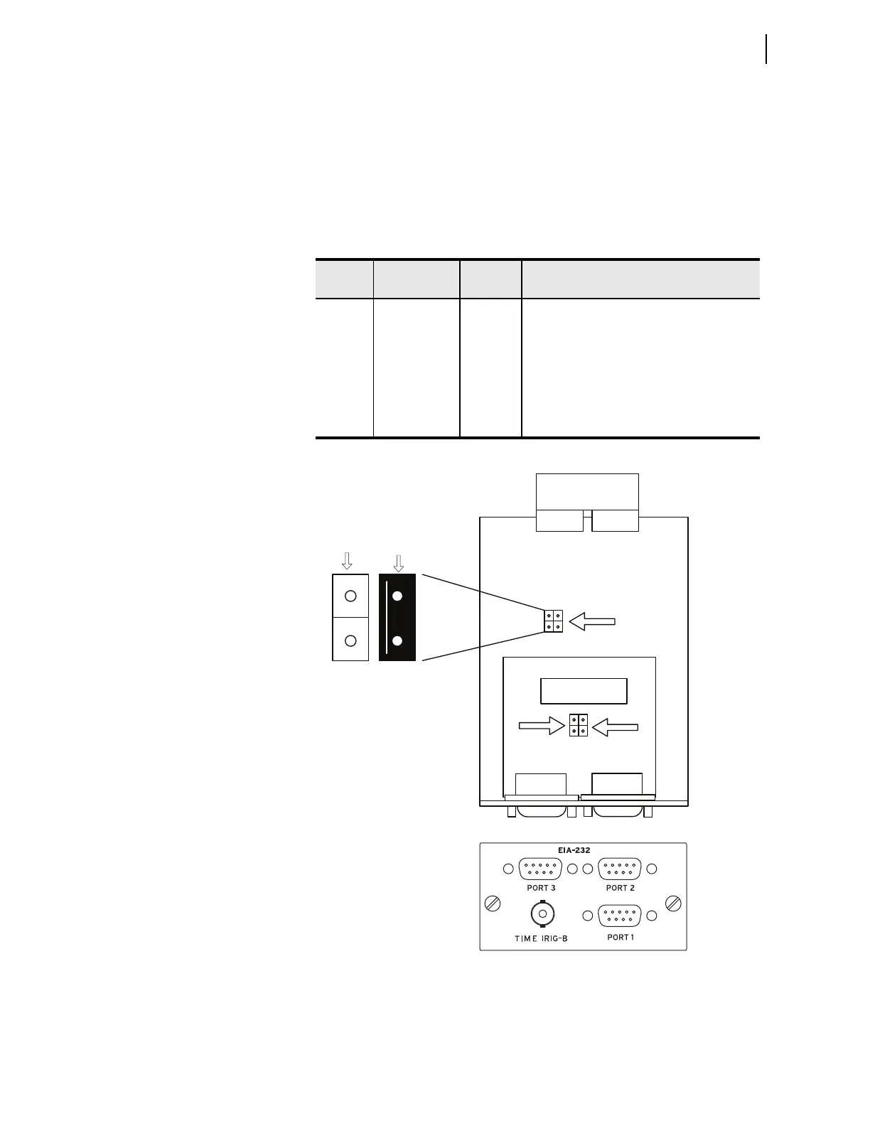
Place jumpers on the EIA-232 board to connect +5 Vdc to Pin 1 of each of the
three rear-panel EIA-232 serial ports. The maximum current available from
this Pin 1 source is 0.5 A. The Pin 1 source is useful for powering an external
modem. Table 2.5 describes the JMP1 and JMP2 positions. Refer to
Figure 2.16 for the locations of these jumpers. The relay ships with JMP1A,
JMP2A, and JMP2B OFF (no +5 Vdc on Pin 1).
Figure 2.16 Main Components of the EIA-232 Board, Showing the Location
of Serial Port Jumpers JMP1 and JMP2
Tab l e 2. 5 S e r i a l Po r t J u m pe rs
Jumper
Label
Jumper A or
Jumper B
Jumper
Position
a
a
ON is the jumper shorting both pins of the jumper. Place the jumper over one pin only for OFF.
Function
JMP1 A OFF
ON
Serial PORT 1, Pin 1 = not connected
Serial PORT 1, Pin 1 = +5 Vdc
B—Not used
JMP2 A OFF
ON
Serial PORT 2, Pin 1 = not connected
Serial PORT 2, Pin 1 = +5 Vdc
JMP2 B OFF
ON
Serial PORT 3, Pin 1 = not connected
Serial PORT 3, Pin 1 = +5 Vdc
A
JMP1
B
JMP2
AB
Port 2 Port 3
Port 1
Jumper ‘A’
Jumper ‘B’
Not used
Port 2
Jumper ‘A’
Port 3
Jumper ‘B’
Rear View
Jumper ONJumper OFF
Top View