P.3.155
Date Code 20151029 Protection Manual SEL-411L Relay
Protection Functions
Series-Compensation Line Logic
The following conditions can aggravate CVT transients:
➤ CVT secondary with a mostly inductive burden
➤ A low C value CVT, as defined by the manufacturer
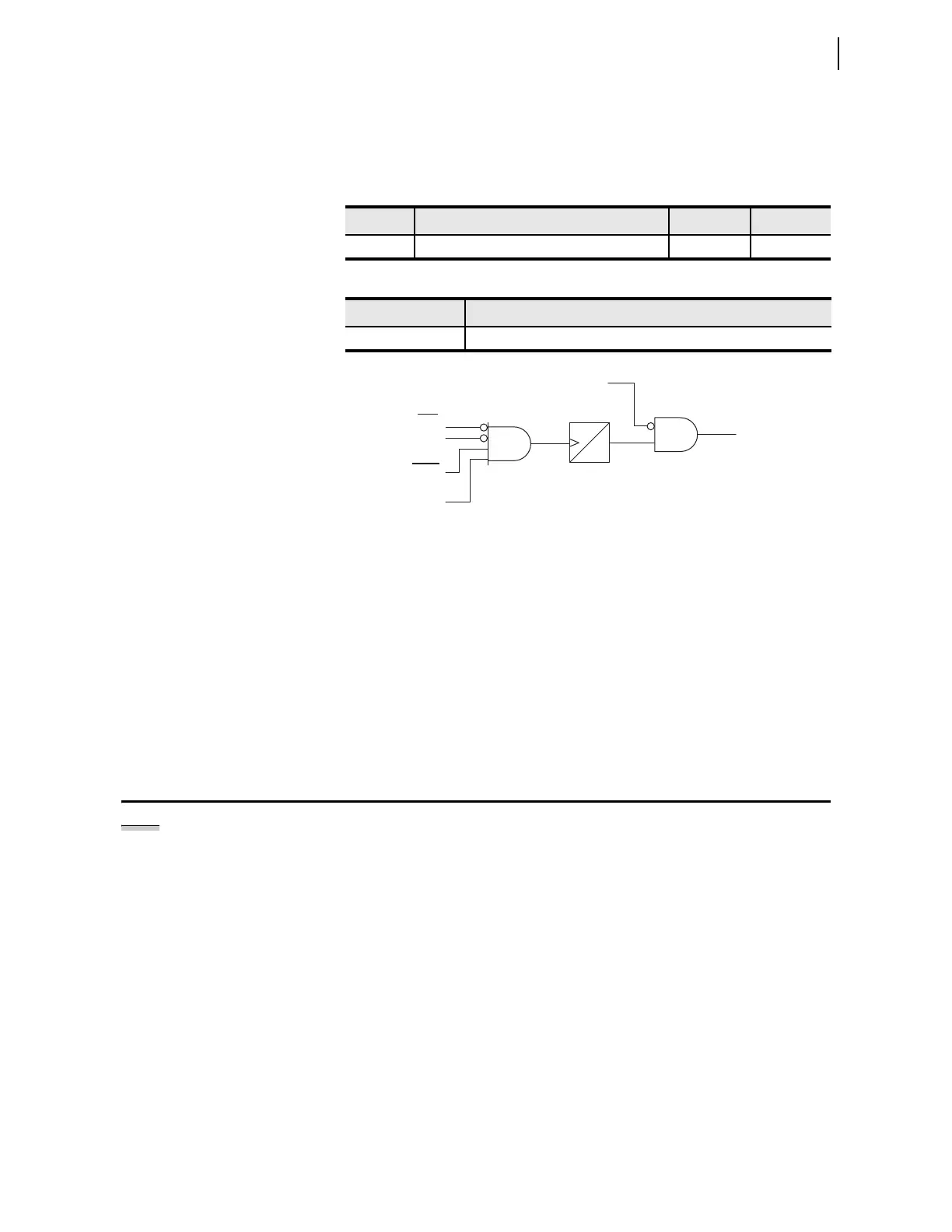
Figure 3.93 CVT Transient Detection Logic
SIR is defined as follows:
Use the Zone 1 distance element reach (Z1MP, Z1MG, or XG1) since the
CVT transient detection logic only supervises Zone 1 distance protection.
Series-Compensation Line Logic
The relay includes logic to detect when a fault is beyond a series capacitor (a
series capacitor can possibly cause Zone 1 overreach). The relay blocks the
Zone 1 elements until the series-compensation logic determines that the fault
is between the relay and the series capacitor (i.e., the fault is on the protected
line section).
The value that you enter for setting XC depends on the position of the series-
compensation capacitor(s) relative to the relay potential transformers.
Capacitors can be on either end of a line, in the middle of a line, or at both
ends of a line. Capacitors that are external to a protected line section can have
an effect if infeed conditions are present.
In applications where there is a series capacitor on an adjacent line, for any
relays on non-compensated lines, set ESERCMP := Y and XC := OFF. This
allows the Zone 1 element to be set to the desired sensitivity, yet still be secure
during the voltage reversal that will occur when a neighboring compensated
line experiences a fault.
Table 3.82 CVT Transient Detection Logic Setting
Name Description Range Default
ECVT CVT transient detection Y, N N
Table 3.83 CVT Transient Detection Logic Relay Word Bit
Name Description
CVTBL CVT transient blocking active
where:
Z
1S
= positive-sequence source impedance
Z
R
= distance element reach
0
1.5
CYC
Distance Calculation
Smoothness
Relay
Word
Bits
3PO
CVTBL
SOTFE
ECVT := Y
SIR > 5 During
Zone 1 Fault
Setting
NOTE: The -0 relay does not provide
series-compensated line protection
logic.