P.3.19
Date Code 20151029 Protection Manual SEL-411L Relay
Protection Functions
87L Theory of Operation
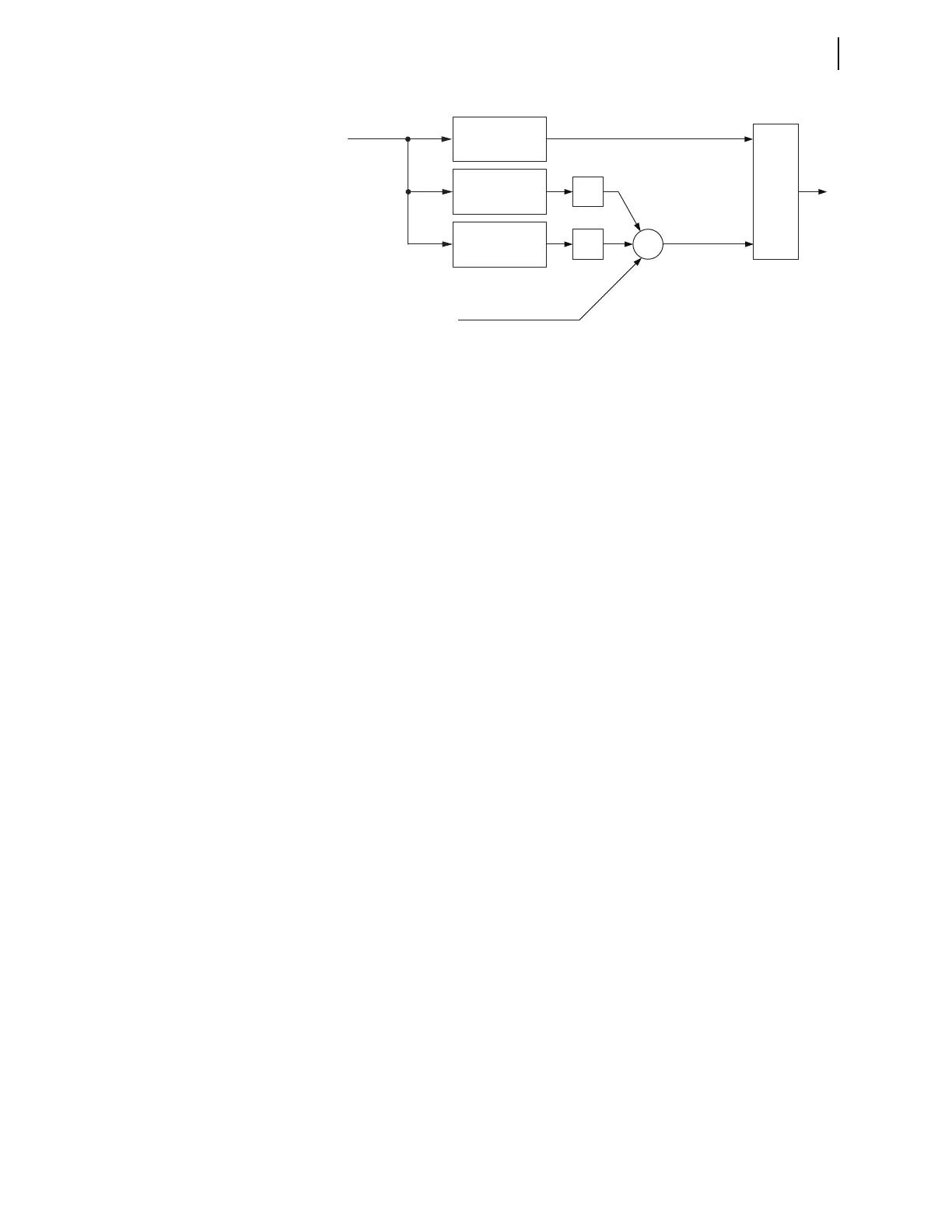
Figure 3.13 Principle of Harmonic Restraint in the Generalized Alpha Plane
Operating Characteristic
87L Differential Applications With In-Line Transformers provides more detail
on 87L operation, application, and settings related to in-line transformers.
Scaling of 87L
Currents and Tap
Calculations
The relay uses the following conventions to scale currents related to 87L
function accommodation of different CT ratios, different CT secondary
nominal currents at various line terminals, in-line transformers, and charging
current compensation while optimizing signal accuracy and resolution.
An understanding of the 1 pu (per-unit) value for the 87L function is
necessary to apply pickup settings and to understand 87L internal logic related
to comparators acting on differential, restraining, and individual currents. In
applications without in-line transformers, 1 pu is the maximum primary
current of any CT configured to be a part of the 87L zone. The relay
determines the 1 pu value and appropriate tap coefficients automatically
according to the ratios and nominal secondary currents of the local current
input terminals (W and X) and user settings specifying the CT primary rating
at the remote terminals. If a remote terminal is a dual-breaker terminal that
uses both W and X current inputs, enter the highest CT primary between the
two CTs as the user setting for the remote CT primary value.
In applications with charging current compensation, enter the line susceptance
in secondary values. The PT ratio that defines the secondary value is the actual
ratio of the voltage transformer the relay uses for charging current
compensation. The CT ratio that defines the secondary value is the highest
ratio of as many as two CTs configured as local inputs to the 87L zone.
In applications with in-line transformers, the 1 pu value is the power
transformer nominal current at a given voltage level. The relay determines the
1 pu value and appropriate tap coefficients automatically according to the
power transformer data (MVA and voltage associated with a given CT input)
and CT data. To allow better optimization of the 87L communications
channel, the relay expects you to enter the minimum ratio between the
transformer nominal current (primary for a given winding) and the CT
nominal current (primary) for any winding/current input combination that
bounds the differential zone.
87L Differential Applications With In-Line Transformers provides more
information and numerical examples for determining settings related to signal
scaling as well as for explaining internal tap calculations that the relay of a
given 87L scheme performs.
Current Data
Alignment
The relay allows alignment of current signal data through the use of the 87L
channel (channel-based mode) or the explicit external time reference the
relays receive (external-time-based mode).
Σ
Instantaneous
Differential, i
DIF
Fundamental
Phasor
2
nd
Harmonic
Magnitude
4th Harmonic
Magnitude
k
2
k
4
Restraining Current
(fundamental), I
RST
Effective
Restraining Current
Generalized Alpha
Plane Algorithm
I
DIF
k