P.12.37
Date Code 20151029 Protection Manual SEL-411L Relay
Bay Control
Predefined Bay Control One-Line Diagrams
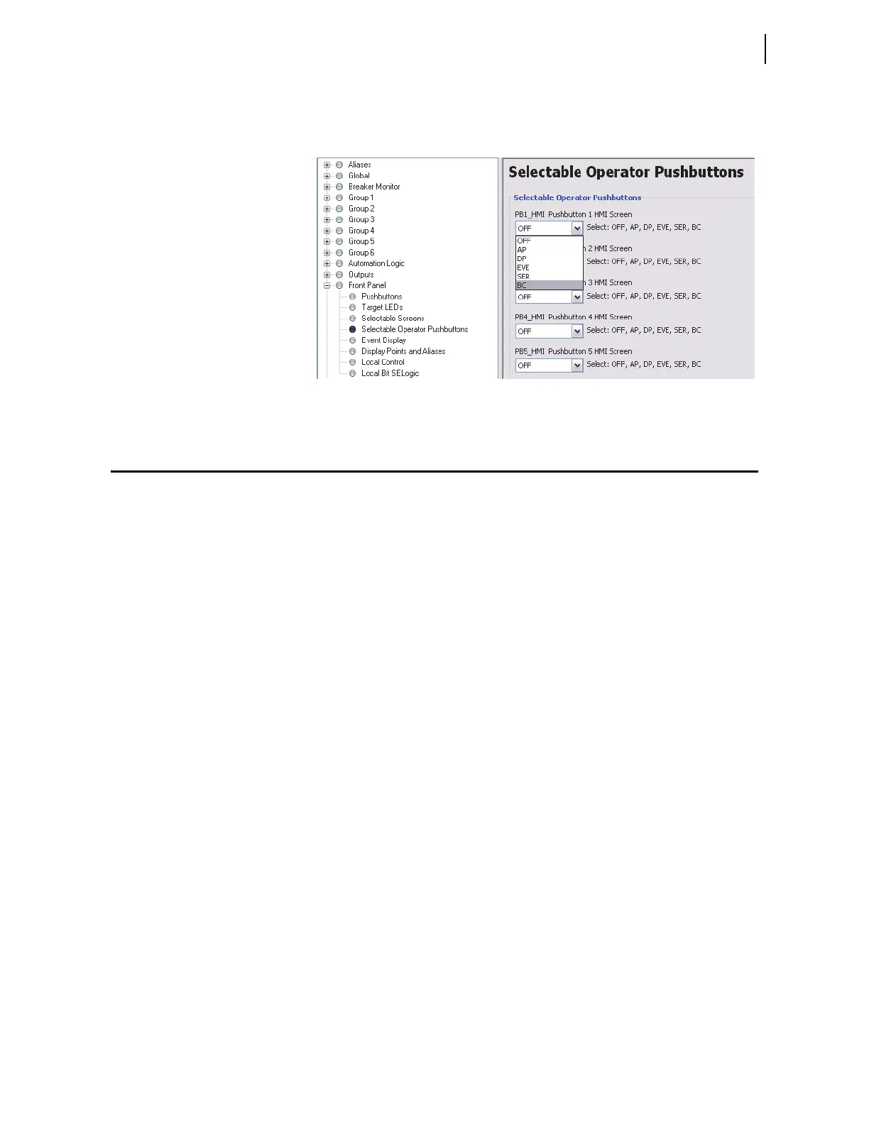
You can also configure an HMI pushbutton to give you direct access to the bay
control screen. Figure 12.29 shows an example of how to configure HMI
Pushbutton 1 by selecting the BC option from the drop-down menu.
Figure 12.29 Configuring PB1_HMI for Direct Bay Control Access
Predefined Bay Control One-Line Diagrams
Configurations
The following pages illustrate all of the predefined busbar and bay control
configurations in the relay defined by the (MIMIC settings). Select the bay
screen that exactly matches the bay configuration being controlled from the
following figures.
➤ Figure 12.30–Figure 12.32: Main Bus and Auxiliary Bus one-
line diagram
➤ Figure 12.33–Figure 12.34: Bus 1, Bus 2, and Transfer Bus
one-line diagram
➤ Figure 12.35: Transfer Bay one-line diagram
➤ Figure 12.36: Tie Breaker Bay one-line diagram
➤ Figure 12.37–Figure 12.38: Main Bus and Transfer Bus one-
line diagram
➤ Figure 12.39–Figure 12.40: Main Bus one-line diagram
➤ Figure 12.41–Figure 12.45: Breaker-and-a-Half one-line
diagram
➤ Figure 12.46–Figure 12.47: Ring Bus one-line diagram
➤ Figure 12.48–Figure 12.51: Double Bus Double Breaker one-
line diagram
➤ Figure 12.52: Source Transfer Bus one-line diagram
➤ Figure 12.53–Figure 12.54: Throw-Over Bus one-line diagram