P.3.258
SEL-411L Relay Protection Manual Date Code 20151029
Protection Functions
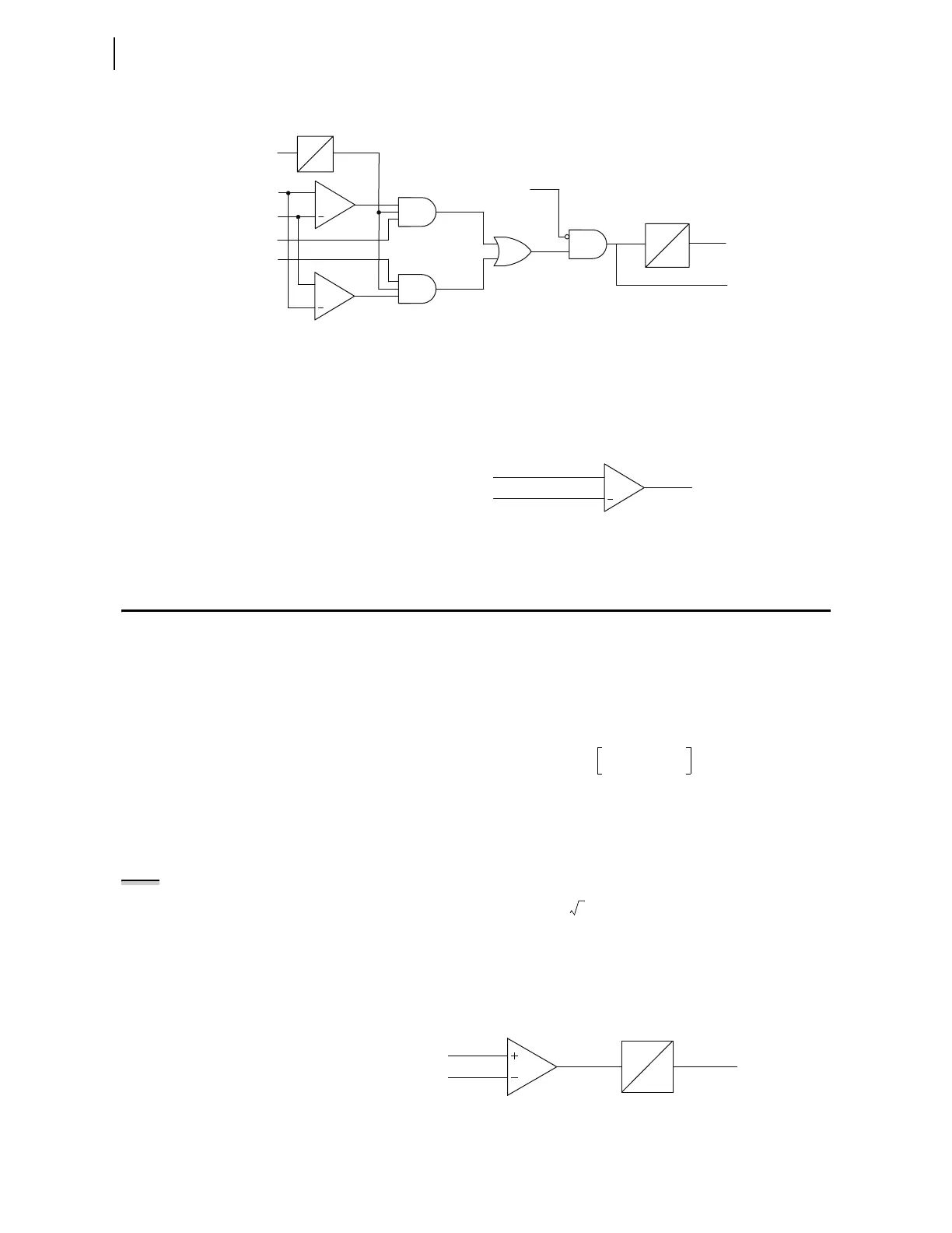
Undervoltage Supervision Logic
Logic
Figure 3.171 Over/Underfrequency Logic
Note that Relay Word bit 27B81 controls all six frequency elements. Relay
Word bit 27B81 asserts to logical 1 and blocks frequency element operations
if the positive-sequence voltage drops below pickup setting 81UVSP. This
control prevents erroneous frequency element operations during system faults.
Figure 3.172 Frequency Source Logic
Undervoltage Supervision Logic
Relay Word bit 27B81, the output of the logic in Figure 3.173, supervises the
frequency elements for system undervoltage conditions. In the logic, the
comparator compares the absolute value of the alpha component voltage
(Valpha) against the 81UVSP setting value. Equation 3.92 shows the equation
for calculating Valpha.
Equation 3.92
Generally, settings VF01, VF02, VF03 correlate to VA, VB, and VC.
Equation 3.93 shows the relationship between the peak amplitude of Valpha
and the root-mean-square (RMS) value of the system voltage phasors for
3-phase voltage inputs.
NOTE: The relay uses the alpha
component voltage to track the
system frequency. To ensure the relay
uses the same voltage for frequency
tracking and frequency elements
undervoltage supervision, the
operating quantity in Figure 3.173 was
changed from the positive-sequence
voltage to the alpha-component
voltage. This change affects firmware
versions R310 and higher and may
require a revision of the 81UVSP
setting.
Equation 3.93
where VRMS is the root-mean-square value of the voltage phasor.
Relay Word bit 27B81 asserts if Valpha falls below the 81UVSP setting value
for longer than a cycle.
Figure 3.173 Undervoltage Supervision Logic
+
FREQP
81DnP
+
81DnP ≥ NFREQ
81DnP < NFREQ
81Dn
81DnT
81DnOVR
81DnUDR
Frequency
Element n
Frequency Timer n
FREQOK
where n = 1, 2, 3, 4, 5, 6
81DnD
0
0
1 cyc
27B81
+
81UVSP
(setting)
27B81
V1AFM
Valpha VF01
VF02
2
--------------
VF03
2
--------------+–=
1.0 cyc
0.0
|Valpha|
81UVSP
27B81