P.7.7
Date Code 20151029 Protection Manual SEL-411L Relay
Front-Panel Operations
Front-Panel Layout
If you enter a Relay Word bit that does not match a valid relay element, the
relay displays:
Unknown relay word reference. If you enter an alias or name
that is too long, the relay displays:
Alias label too long.
The relay displays alarm points in a similar fashion as the SER. As many as 19
characters of the given alias are displayed, with a character reserved for the
“*.” The asterisk denotes if the element is asserted. Initially, an alarm point
must be asserted in order to be displayed; after the corresponding element
deasserts, the asterisk is removed, but the alias is not. The relay displays alarm
points in reverse chronological order, just as in the SER, with the most
recently asserted alarm displayed on the top. Deasserted alarms may be
removed from the display with user acknowledgment, as shown in
Example 7.1.
EXAMPLE 7.1 Creating an Alarm Point
Alarm points screens provide operator feedback about the status of
system conditions. An alarm points screen contains 11 alarm points;
this example demonstrates a method to set the alarm point message
that is shown in Figure 7.5. This example is based on the Relay Word
bit IN201 asserting when circuit breaker 1 is in an alarm condition.
In the Report settings (SET R), enter the following after the SER Points
line 1 prompt:
1: IN201,"Circuit BK1 SF6 Gas","Alarm","Normal","Y"
The circuit breaker alarm condition is indicated by the set state,
“Alarm,” and the circuit breaker normal condition is indicated by the
clear state “Normal.” The HMI Alarm parameter is set to “Y” in order
to enable alarm points screen display of this element.
While in the scrolling mode, the assertion of IN201 will cause
Figure 7.5 to automatically display. Upon the deassertion of IN101, the
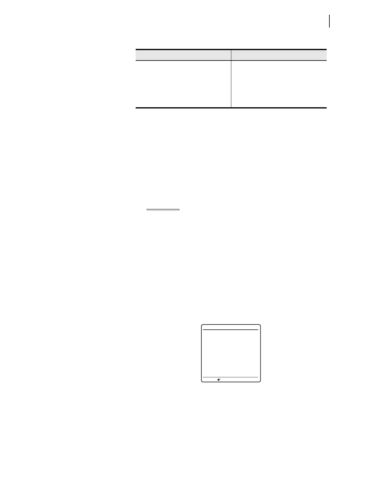
asterisk will disappear, as in Figure 7.6.
Figure 7.6 Deasserted Alarm Point
Pressing the ENT pushbutton will allow the user to acknowledge and
clear deasserted alarms. Before clearing, you will be prompted to
confirm that this is the intended action, as shown in Figure 7.7.
Table 7.3 SER Point Settings
Description Range
Relay Word Bit Any valid relay element
Reporting Name 20-character maximum ASCII string
Set State Name (logical 1) 20-character maximum ASCII string
Clear State Name (logical 0) 20-character maximum ASCII string
HMI Alarm Y, N
Circuit BK1 SF6 Gas
ALARM POINTS
Press to acknldge