P.1.9
Date Code 20151029 Protection Manual SEL-411L Relay
Introduction and Specifications
Applications
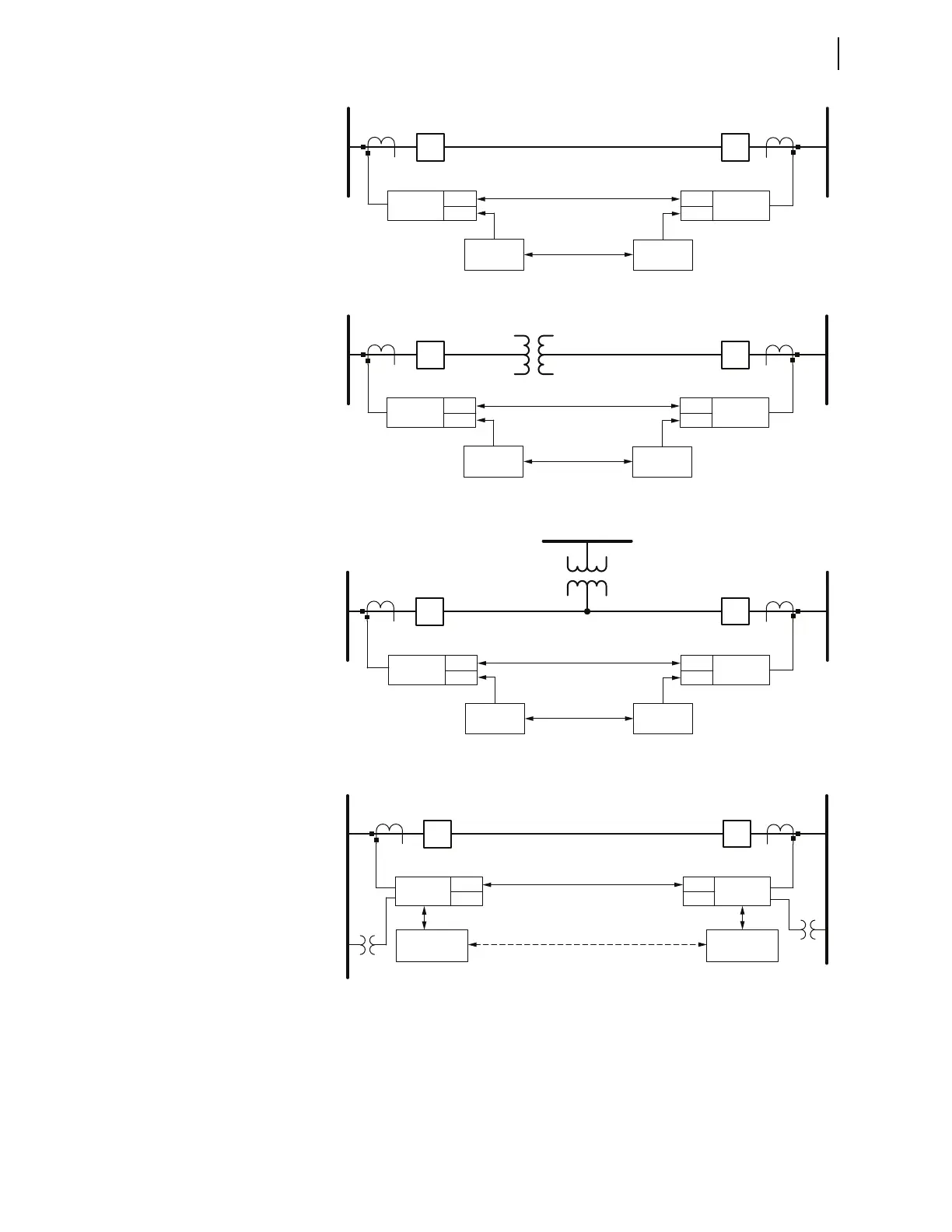
Figure 1.2 Two-Terminal Application With Hot Standby Channel
Figure 1.3 Two-Terminal Application With In-Line Power Transformer and Hot
Standby Channel
Figure 1.4 Two-Terminal Application With Hot Standby Channel and Tapped
Load (Load Significantly Less Than Through-Current)
Figure 1.5 Two-Terminal Application With Voltage Inputs
Relay
Dedicated Fiber
Hot Standby
Channel
Bay 1
Bay 2
Bay 1
Bay 2
Relay
Digital
Multiplexer
Digital
Multiplexer
Relay
Dedicated Fiber
Hot Standby
Channel
Bay 1
Bay 2
Bay 1
Bay 2
Relay
Digital
Multiplexer
Digital
Multiplexer
Relay
Dedicated Fiber
Hot Standby
Channel
Bay 1
Bay 2
Bay 1
Bay 2
Relay
Digital
Multiplexer
Digital
Multiplexer
Relay Relay
Dedicated Fiber
Backup Teleprotection Channel
Bay 1 Bay 1
Teleprotection
Equipment
Teleprotection
Equipment