P.9.8
SEL-411L Relay Protection Manual Date Code 20151029
Monitoring and Metering
Circuit Breaker Monitor
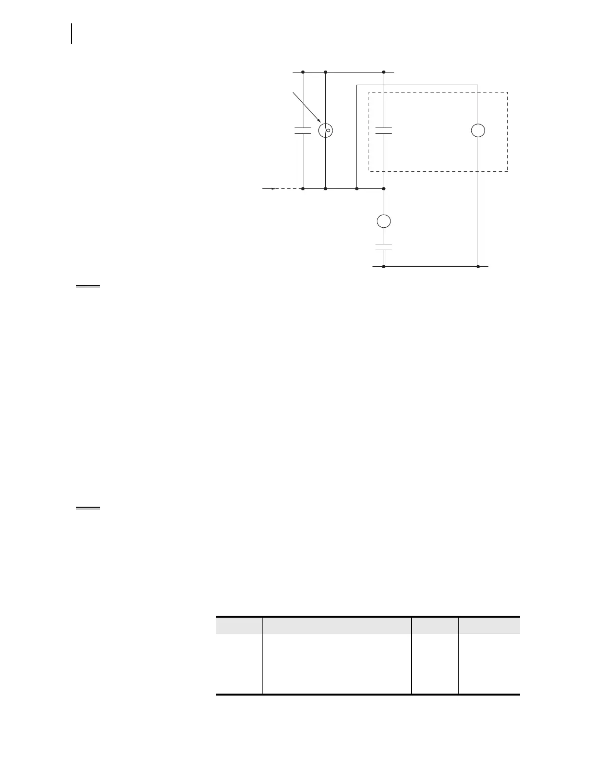
Figure 9.4 Trip Bus Sensing With Relay Input IN206
Many U.S. substation trip bus configurations have an incandescent
trip indicator lamp from the battery + terminal to the trip bus. This
lamp presents an impedance that can provide sufficient “pull-up” on
the trip bus to falsely assert the control input. The worst case for this
condition occurs when the circuit breaker is open (auxiliary circuit
breaker (52A) contact in Figure 9.4 is open). You can change the
input debounce time IN206PU for slow or noisy mechanical switches;
the default debounce time of 1/8 cycle should be sufficient for most
trip bus arrangements.
In the SET G (GLOBAL) command or in the
ACSELERATOR QuickSet
Global > Control Inputs Settings tree view, confirm that the debounce time
(setting IN206PU and IN206DO) are correct for your trip bus control
voltage. You must enable independent control input conditioning by
using Global setting EICIS. Enter these settings:
EICIS := Y Independent Control Input Settings (Y, N)
IN206PU := 0.1250 Input IN206 Pickup Delay (0.0000–5 cyc)
IN206DO := 0.1250 Input IN206 Dropout Delay (0.0000–5 cyc)
BM1TRPA := IN206 Breaker Monitor Trip—BK1 (SELOGIC Equation)
Use this procedure to cause the circuit breaker monitor to initiate for
either external or internal Circuit Breaker 1 A-phase trips.
NOTE:
In the following discussion,
three elements are specified. There is
one element for each phase: A, B,
and C).
Circuit Breaker Monitor Close Initiation Settings: BM1CLS. The
relay employs SEL
OGIC control equations to initiate the circuit breaker
monitor duration timers for close functions. For Circuit Breaker 1, this setting
is BM1CLS. These SEL
OGIC control equations use Relay Word bits to
determine when the circuit breaker monitor times mechanical closing,
electrical closing, and pole scatter. Table 9.5 shows the factory default settings
for circuit breaker monitor close initiation.
Other
External
Trips
CS/T
(Control Switch Trip)
52A
Trip
Coil
(+)
(-)
IN206
Relay
OUT201 := TRIP
TC
Trip Bus
Incandescent Lamp
NOTE: See Control Inputs on
page P.2.5 for recommended control
input settings.
Table 9.5 Circuit Breaker Monitor Close SELOGIC Control Equations
Name Description Default Comment
a
a
See Table 9.1.
BM1CLSA Breaker Monitor 1 close equation BK1CL If BK1TYP := 3
BM1CLSA Breaker Monitor 1 A-phase close equation BK1CL If BK1TYP := 1
BM1CLSB Breaker Monitor 1 B-phase close equation BM1CLSA If BK1TYP := 1
BM1CLSC Breaker Monitor 1 C-phase close equation BM1CLSA If BK1TYP := 1