P.3.99
Date Code 20151029 Protection Manual SEL-411L Relay
Protection Functions
87L Differential Elements
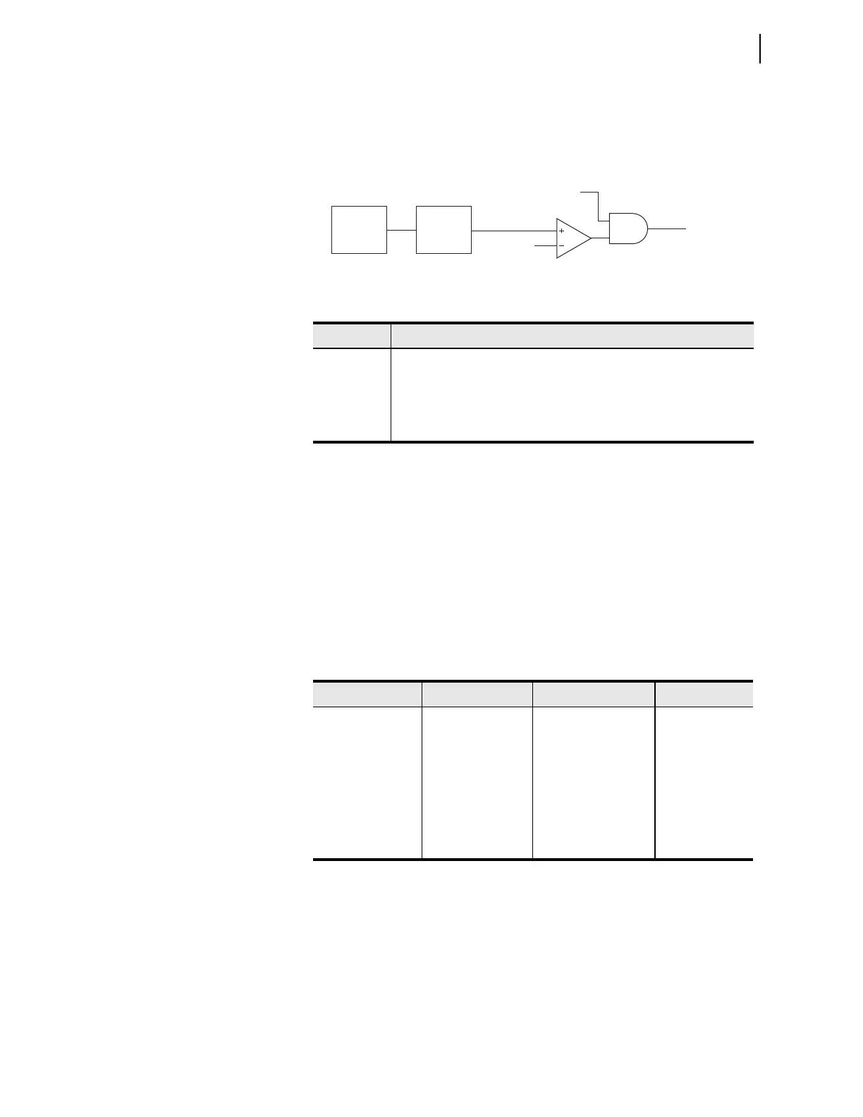
relay is healthy, and then reset the second level watchdog counter with
command COM 87L WD C at the calibration level. The calibration level
setting 87WDOG2 can be used to change the 87L inhibit threshold from the
default value of 10. Figure 3.51 shows a diagram of the Level 2 watchdog
monitor.
q See Figure 3.194.
Figure 3.51 Level 2 Watchdog Monitor Diagram
For information on channel configuration, monitoring, alarming, and logic see
87L Communication and Timing.
87L Element
Operating Time
Curves
Table 3.40 shows operating times for the current line differential elements
when using serial communications, and Table 3.41 when using Ethernet
communications. The diagrams show the average operating times (minimum
of twelve trials) for each element. Operating times include output contact
closure time (high-speed contact outputs). Tests were performed for 1, 2, 4, 8,
10, 12, 15 and 20 multiples of pickup setting. At 20 times the setting, the
deviation was 1.2 ms. These tests do not include prefault load current or fault
resistance. Operating times are the same for 50 Hz and 60 Hz.
Table 3.39 87L Watchdog Relay Word Bits
Name Description
87ALARM 87L watchdog logic alarm (87L operational, user-resettable)
87ERR1 87L watchdog logic Stage 1 operation (channel related issues, 87L inhib-
ited, user-resettable)
87ERR2 87L watchdog logic Stage 2 operation (all issues, 87L inhibited, user-
resettable)
Spurious 87L
Assertions
Second
Level
Counter
87WDOG2
(Calibration Setting)
87ERR2
(Relay
Word Bit)
87WDCT2
(Analog Quantity)
EWDSEC
(SELOGIC Equation)
q
To Blocking
Logic
Table 3.40 Current Line Differential Elements Operating Times (Cycles)—Serial
Communication
Multiples of Pickup Phase Negative-Sequence Zero-Sequence
1 1.64 1.76 1.78
2 1.23 1.32 1.35
4 0.87 1.01 1.02
8 0.77 0.88 0.90
10 0.75 0.87 0.89
15 0.73 0.87 0.87
20 0.69 0.83 0.83