P.4.53
Date Code 20151029 Protection Manual SEL-411L Relay
Autoreclosing and Synchronism-Check
Synchronism Check
PT Connections
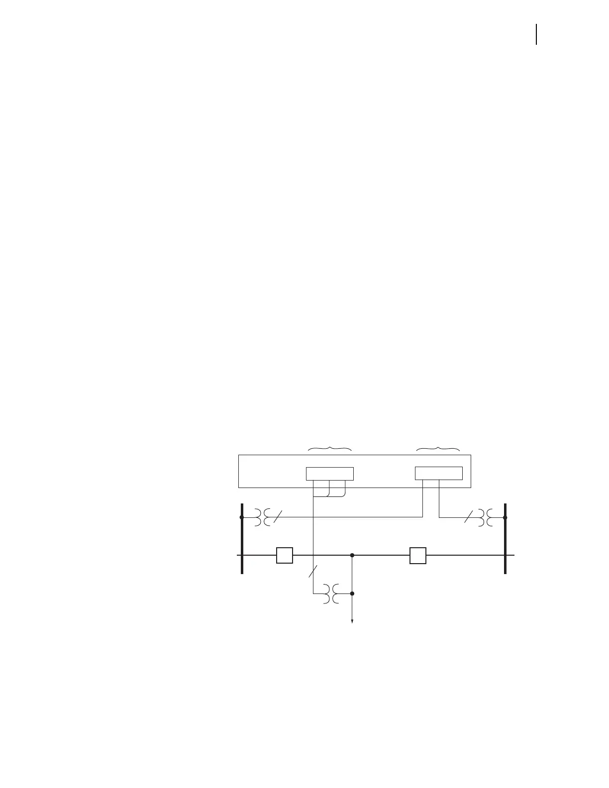
Figure 4.23 is an example of connecting PTs to the relay for two circuit
breakers. The Bus 1 and Bus 2 single-phase voltages are connected to relay
voltage inputs VAZ and VBZ, respectively. They could just as easily have
been connected to any of the other voltage inputs. The voltage connected to
voltage input VAZ (setting SYNCS1 := VAZ; see Figure 4.23) is not
necessarily from A-phase on Bus 1. Likewise, the voltage connected to
voltage input VBZ (setting SYNCS2 := VBZ; see Figure 4.23) is not
necessarily from B-phase on Bus 2. The connection can be from any phase-to-
neutral or phase-to-phase voltage (as long as you do not exceed the relay
voltage input ratings). Settings in the relay compensate for any steady-state
magnitude or angle difference with respect to a synchronism-check voltage
reference, as discussed next in this example.
Three-phase line voltages are connected to relay voltage inputs VAY, VBY,
and VCY (these voltage inputs are also used for distance elements fault
location, loss-of-potential, load encroachment, and directionality). Only one
of these single-phase voltage inputs is designated for use in synchronism-
check. In this example, this voltage input is also designated the synchronism-
check voltage reference (setting SYNCP := VAY; see Figure 4.23). As the
synchronism-check voltage reference, the relay makes all steady-state
magnitude and angle adjustments for the Bus 1 and Bus 2 synchronism-check
voltages (connected to voltage inputs FAZ and FBZ, respectively, as discussed
in the preceding paragraph) with respect to this designated reference line
voltage, VAY, as discussed later in this example.
For a single-circuit breaker application, you can use either bus-side potentials
or line-side potentials for line relaying; connect the three-phase voltage source
to potential inputs VAY, VBY, and VCY. If a single-phase voltage source is
available on the other side of the circuit breaker for synchronism-check,
connect the source to potential input VAZ, VBZ, or VCZ.
Figure 4.23 Example Synchronism-Check Voltage Connections to the Relay
Voltage Magnitude
and Angle
Compensation
The Figure 4.23 example continues in Figure 4.24. The Figure 4.24 example
demonstrates possible voltage input connections (presuming ABC phase
rotation). The synchronism-check voltage reference (V
P
) is from the A-phase
voltage (V
A
) of the line. You can connect phase-to-phase voltage V
BC
originating from Bus 1, and connect phase-to-neutral voltage V
C
from Bus 2.
Thus, Bus 1 voltage V
BC
lags synchronism-check voltage reference V
P
by 90
Bus 2
Bus 1
Relay Rear Panel
(partial)
Three-phase Line
Voltage Connections
Separate, Single-phase
Bus/Source
Voltage Connections
Line
BK2
BK1
VAY VBY VCY
VAZ VBZ VCZ
1
3
1