P.3.11
Date Code 20151029 Protection Manual SEL-411L Relay
Protection Functions
87L Theory of Operation
Also note that the true instantaneous restraining signal is unavailable to the
external fault detection algorithm. The algorithm calculates the instantaneous
restraining signal as the sum of absolute values of the local currents and the
received remote currents. For example, in a dual-breaker application with two
remote relays, the equation becomes as follows (see Figure 3.2).
Equation 3.10
If the remote terminal is a dual-breaker terminal, the received instantaneous
current, i
REM1
for example, is the sum of the two currents; it may not signify
an external fault should the fault happen at that remote terminal.
For example, as in Figure 3.2, the instantaneous restraining current the T1
relay calculation is effectively as follows.
Equation 3.11
The previous signal may fail to detect an external fault current close to remote
terminal T2 with the fault current flowing in CT3 and out of CT4.
At the same time, the instantaneous restraining current the T2 relay uses will
detect an external fault occurring close to the T2 terminal. Calculation of the
instantaneous restraining current of the T2 relay is as follows.
Equation 3.12
The previous term includes CT3 and CT4 currents individually, so the T2
relay will detect a through fault in the CT3–CT4 path.
In general, a given relay will detect an external fault, within the sensitivity
limits of the external fault detection algorithm, for all external faults close to
the associated line terminal. Depending on the exact current flow pattern
through the line terminals toward the external fault, the relay may or may not
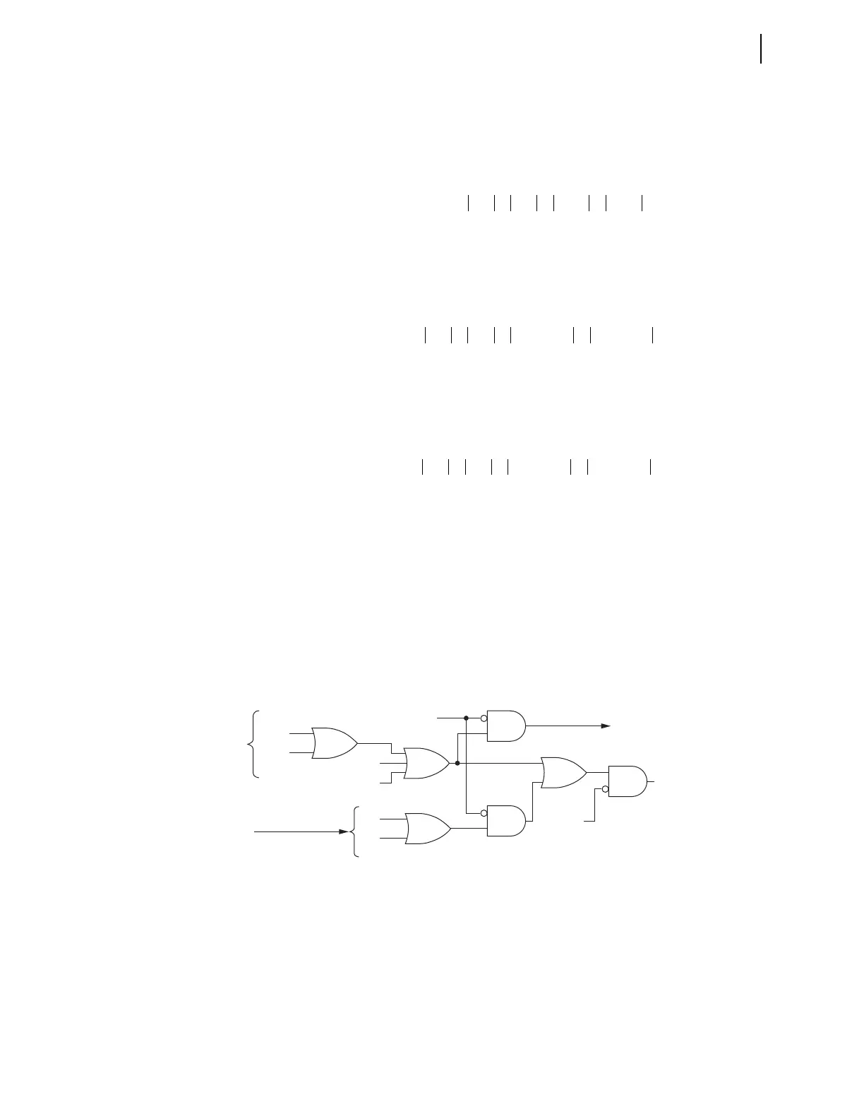
detect external faults close to the remote line terminals. To solve this problem,
relays (as in Figure 3.5) exchange external fault detected (EFD) bits to inform
all relay terminals if any of the relays detect an external fault. Relays block
EFD signaling if a given relay is in the stub bus condition. During the stub bus
condition, the local 87L zone and the line differential zones are separate
entities that should not share signals with each other about external faults.
Figure 3.5 Sharing the EFD Bits Among Relay Terminals
Figure 3.6 shows a simplified logic diagram of the dc saturation path of the
algorithm. The logic checks if the dc component in any of the local 87L zone
currents is relatively high, as compared with the CT nominal and the ac
component at the time. If the dc component is high, and the differential
current is low compared with the restraining current, EFD
DC
asserts in
anticipation of possible CT saturation resulting from overfluxing because of
the dc component. As with the ac saturation detection algorithm, relays share
i
RST
i
CT1
i
CT2
i
REM1
i
REM2
++ +=
i
RST
i
CT1
i
CT2
i
CT3
i
CT4
+ i
CT5
i
CT6
+++ +=
i
RST
i
CT3
i
CT4
i
CT1
i
CT2
+ i
CT5
i
CT6
+++ +=
EFDA
AC
EFDA
DC
To Outgoing Packets
Remote Terminals
(Incoming Packets)
Local Terminal
Stub Bus
EFDB
EFDA
EFDC
EFD1
EFD2
...
87TEST
87EFD