P.2.32
SEL-411L Relay Protection Manual Date Code 20151029
Installation
Connection
Power Connections
The terminals labeled POWER on the rear panel (#Z29 and #Z30) must connect
to a power source that matches the power supply characteristics that your relay
specifies on the rear-panel serial number label. (See Power Supply on
page P.1.13, for complete power input specifications.) For the relay models
that accept dc input, the serial number label specifies dc with the symbol
shown in Figure 2.27.
NOTE: The combined voltages
applied to the POWER and MONITOR
terminals must not exceed 600 V (rms
or dc).
The POWER terminals are isolated from chassis ground. Use 16–14 AWG
(1.5 mm
2
–2.1 mm
2
) size wire to connect to the POWER terminals. Connection
to external power must comply with IEC 60947-1 and IEC 60947-3 and must
be identified as the disconnect device for the equipment.
Place an external disconnect device, switch/fuse combination, or circuit
breaker in the POWER leads for the relay; this device must interrupt both the hot
(H/+) and neutral (N/–) power leads. The current rating for the power
disconnect circuit breaker or fuse must be 20 A maximum.
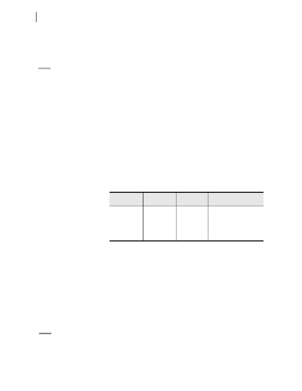
Operational power is internally fused by power supply fuse F1. Table 2.7 lists
the relay power supply fuse requirements. Be sure to use fuses that comply
with IEC 127-2.
You can order the relay with one of two operational power input ranges listed
in Table 2.7. Each supply voltage range represents a power supply ordering
option.
Note that each power supply range covers two widely used nominal input
voltages. The relay power supply operates from 30 Hz to 120 Hz when ac
power is used for the POWER input.
The relay accepts dc power input for all power supply models. The
48–125 Vdc supply also accepts 110–120 Vac; the 125–250 Vdc supply also
accepts 110–240 Vac. When connecting a dc power source, you must connect
the source with the proper polarity, as indicated by the + (terminal #Z29) and
– (terminal #Z30) symbols on the power terminals. When connecting to an ac
power source, the + terminal #Z29 is hot (H), and the – terminal #Z30 is
neutral (N).
Each model of the relay internal power supply exhibits low power
consumption and a wide input voltage tolerance. For more information on the
power supplies, see Power Supply on page P.1.13.
Monitor Connections
(DC Battery)
The relay monitors two dc battery systems. For information on the battery
monitoring function, see Station DC Battery System Monitor on page P.9.20.
Connect the positive lead of Battery System 1 to Terminal #Z25 and the
negative lead of Battery System 1 to Terminal #Z26. (Usually Battery
System 1 is also connected to the rear-panel POWER input terminals.) For
Battery System 2, connect the positive lead to Terminal #Z27, and the negative
lead to Terminal #Z28.
Table 2.7 Fuse Requirements for the Power Supply
Rated Voltage
Operational
Voltage Range
Fuse F1 Fuse Description
48–125 V or
110–120 Vac
38–140 Vdc or
85–140 Vac
(30–120 Hz)
125–250 V or
110–240 Vac
85–300 Vdc or
85–264 Vac
(30–120 Hz)
T3.15AH250V 5x20 mm, time-lag, 3.15 A,
high break capacity, 250 V
NOTE: The combined voltages
applied to the POWER and MONITOR
terminals must not exceed 600 V
(rms or dc).