P.14.18
SEL-411L Relay Protection Manual Date Code 20151029
SELOGIC Control Equation Programming
SEL
OGIC Control Equation Elements
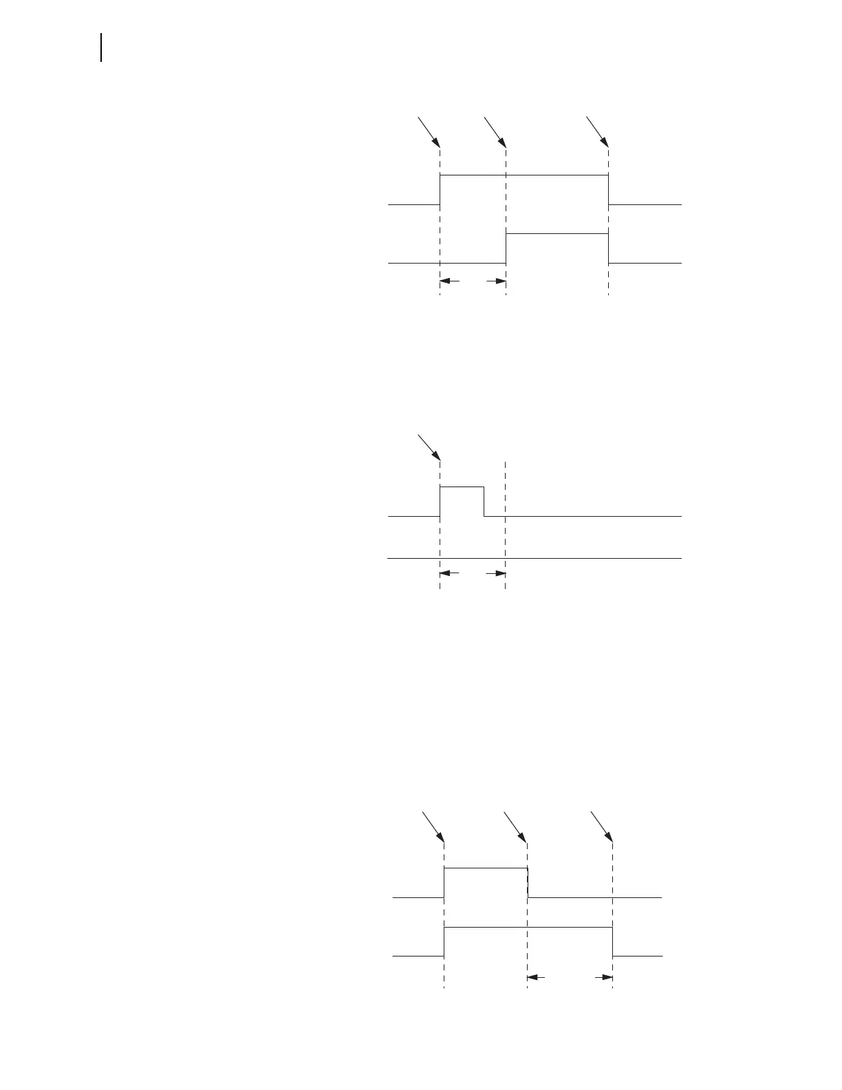
Figure 14.3 Conditioning Timer With Pickup and No Dropout Timing Diagram
If the Pickup Time is not satisfied, the timer Output never turns on, as
illustrated in Figure 14.4. If the input reasserts again, one or more processing
cycles later, the conditioning timer pickup timer begins timing again from
zero.
Figure 14.4 Conditioning Timer With Pickup Not Satisfied Timing Diagram
A conditioning timer output turns off when the input turns off and the Dropout
Time expires. An example timing diagram for a conditioning timer, PCT02,
with a Pickup Time setting of zero and a Dropout Time setting greater than
zero is shown in Figure 14.5. Because the Pickup Time, PCT02PU, setting is
zero, the Output, PCT02Q, turns on when the Input, PCT02IN, turns on. The
Output turns off after the Input turns off and the Dropout Time, PCT02DO,
expires. If the input reasserts before the dropout time expires, the dropout
timer resets so it begins timing again from zero when the input drops out
again.
Figure 14.5 Conditioning Timer With Dropout and No Pickup Timing Diagram
PCT01IN
PCT01Q
Input Changes
from 0 to 1
Input Changes
from 1 to 0
Pickup
Time
PCT01PU
Pickup Time
Expires
PCT01IN
PCT01Q
Input Changes
from 0 to 1
Pickup
Time
PCT01PU
PCT02IN
PCT02Q
Input Changes
from 0 to 1
Input Changes
from 1 to 0
Dropout Time
Expires
Dropout Time
PCT02DO