P.11.30
SEL-411L Relay Protection Manual Date Code 20151029
Testing and Troubleshooting
Checking Relay Operation
Step 3. Display the 50Q1 Relay Word bit on the front-panel LCD
screen.
a. Access the front-panel LCD
MAIN MENU.
b. Highlight
RELAY ELEMENTS and press ENT.
c. Press ENT to go to the
ELEMENT SEARCH submenu of
Figure 11.14.
d. Use the navigation keys to highlight
5 and then press
ENT to enter characters in the text input field.
e. Enter the 0, Q, and 1 characters in turn.
f. Highlight
ACCEPT and press ENT.
The relay displays the screen containing the 50Q1
element, as shown in Figure 11.15.
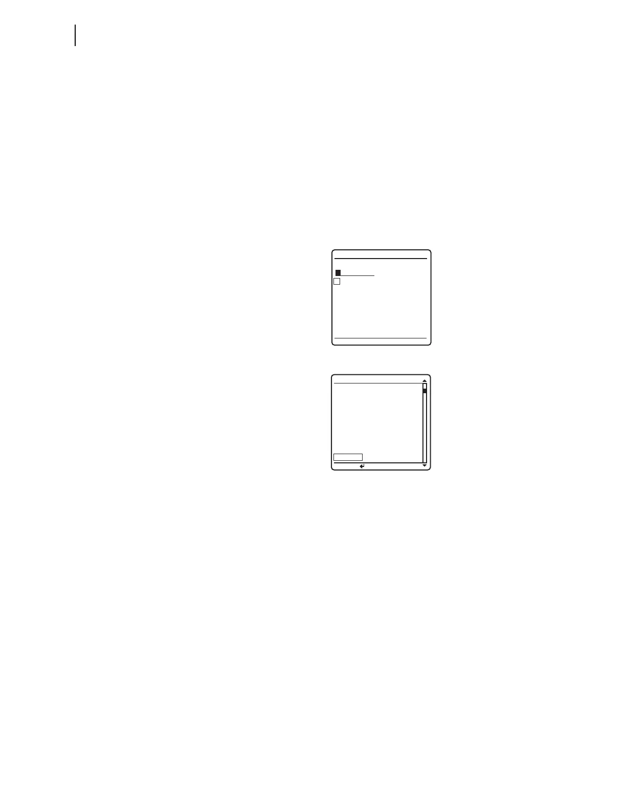
Figure 11.14 ELEMENT SEARCH Screen
Figure 11.15 RELAY ELEMENTS Screen Containing Element 50Q1
Step 4. Connect a test source to the relay.
a. Set the current output of a test source to zero output
level.
b. Connect a single-phase current output of the test source
to the IAW analog input (see Secondary Circuits on
page P.2.4).
Step 5. Increase the current source to produce a current magnitude
greater than 1.00 A secondary in the relay.
You will see that the 50Q1 element state changes on the LCD
screen from 50Q1 = 0 to 50Q1 = 1.
Negative-Sequence
Directional Element
for Phase Faults
The relay features a phase directional element (represented by Relay Word
bits F32P/R32P) to supervise the phase distance elements and to control phase
directional elements. The negative-sequence directional element, F32Q/R32Q,
is a part of the phase directional element, F32P/R32P. Whenever the negative-
sequence directional element asserts, the phase directional element asserts.
The relay also contains a ground directional element, F32G/R32G, for
directional control of the ground distance elements and ground overcurrent
elements.
ELEMENT SEARCH
A B C D E F
G H I J K L
M N O P Q R
S T U V W X
Y Z 0 1 2 3
4 5 6 7 8 9
-
ACCEPT BACKSPACE
PRESS to search
RELAY ELEMENTS
SEARCH
ROW 26 ROW 27
67Q4
=0 * =0
67Q3
=0 * =0
67Q2 =0 * =0
67Q1 =0 * =0
50Q4 =0 67Q4T =0
50Q3 =0 67Q3T =0
50Q2 =0 67Q2T =0
50Q1 =0 67Q1T =0