P.3.18
SEL-411L Relay Protection Manual Date Code 20151029
Protection Functions
87L Theory of Operation
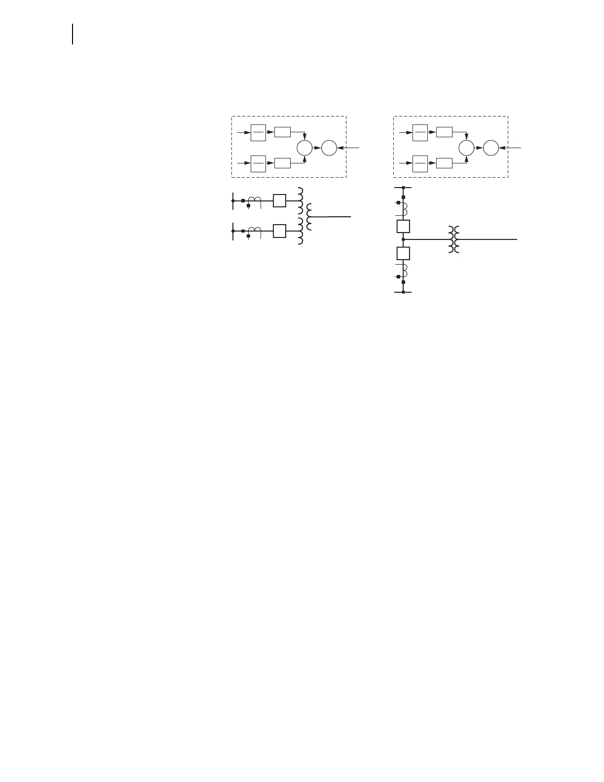
For windings connected as dual-breaker terminations, the settings for both
current inputs are identical because they measure the same transformer
winding (see Figure 3.12).
Figure 3.12 The Relay Allows Different Transformer Windings for each
Measured CT (a) as Well as Dual-Breaker Terminations of the In-Line
Transformer Windings (b)
Scaling of 87L Currents and Tap Calculations explains scaling and TAP
settings, including in-line transformer applications.
The relay uses Equation 3.22 to transform the measured currents at the very
early stage of signal processing. This operation applies to measured samples,
magnitudes used for restraining in the generalized Alpha Plane, calculated line
charging currents, etc. The relay can therefore execute the remainder of the
algorithm with no additional alternations (87L elements, external fault
detection, charging current compensation, etc.). In particular, the 87LP and
87LQ elements are available to provide phase and sensitive negative-sequence
differential protection for the line and transformer according to the
generalized Alpha Plane operating characteristic.
The relay applies harmonic blocking to cope with power transformer
overexcitation conditions. The harmonic blocking logic measures the levels of
harmonics in the differential current, second, fourth, and fifth harmonics for
inrush and overexcitation respectively, relative to the fundamental frequency
component in the differential current. It asserts a block signal if harmonic
levels exceed user-selected thresholds.
The relay supports harmonic blocking and/or restraint for power transformer
magnetizing inrush conditions. The harmonic restraint logic for the
magnetizing inrush conditions adds second and fourth harmonics, with
selected multipliers, to the restraining signal of the 87LP function. The relay
uses second harmonic also to block the negative-sequence differential
element, 87LQ, if the harmonic level exceeds the user-selected threshold. The
user-selected coefficients should be appropriate so that the total restraint is
sufficient to hold back the function under the worst-case scenario of
transformer energization. This restraining action propagates through the
generalized Alpha Plane operating principle, as Figure 3.13 illustrates.
87
L+T
CT1
CT2
CT1
CT2
∑
Relay
[T
1
]
1
TAP
1
i
CT2
i
CT1
[T
2
]
1
TAP
2
87
L+T
∑
Relay
[T]
1
TAP
1
i
CT2
i
CT1
[T]
1
TAP
2
(a)
(b)