P.2.37
Date Code 20151029 Protection Manual SEL-411L Relay
Installation
Connection
Step 10. Replace the battery with an exact replacement.
Use a 3 V lithium coin cell, Ray-O-Vac
®
No. BR2335 or
equivalent. The positive side (+) of the battery faces up.
Step 11. Replace the top cover and ensure that all seven screws were
properly tightened.
Step 12. Reinstall the relay front-panel cover.
Step 13. Reconnect any serial cables that you removed from the EIA-232
PORTS in the disassembly process.
Step 14. Set the relay date and time via the communications ports or
front panel (see Making Simple Settings Changes on
page P.10.13).
Step 15. Follow your company standard procedure to return the relay to
service.
Communication Ports
The relay has three rear-panel EIA-232 serial communications ports labeled
PORT 1, PORT 2, and PORT 3 and one front-panel port, PORT F. For information on
serial communications, see Establishing Communication on page P.10.4,
Serial Communication on page C.1.2, and Serial Port Hardware Protocol on
page C.2.1.
In addition, the relay supports as many as two serial communications ports
dedicated to the 87L function labeled as Bay 1 and Bay 2.
The rear panel also features a Port 5 for an optional Ethernet card. For
additional information about communications topologies and standard
protocols that are available in the relay, see Communications Network
Connections, Section 3: SEL Communications Processor Applications in the
Communications Manual, Section 4: DNP3 Communications in the
Communications Manual, and Section 5: IEC 61850 Communications in the
Communications Manual.
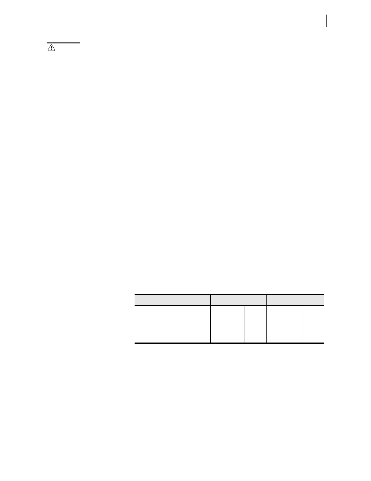
The relay provides communications for the functions shown in Table 2.8.
Figure 2.31 shows the general four-card layout of the relay. Bay 1 and Bay 2 are
for 87L current differential protection when using serial communication. The
communications medium is either copper or fiber. Bay 3 holds the card
dedicated to Ethernet communication. There are four ports on this card: two
for general engineering access (Port 5C and Port 5D) and two for 87L current
differential protection when using Ethernet communication. Bay 4 holds the
three EIA-232 serial communications ports and the IRIG-B port.
There is danger of explosion if the
battery is incorrectly replaced.
Replace only with Ray-O-Vac® no.
BR2335 or equivalent recommended
by manufacturer. See Owner's Manual
for safety instructions. The battery
used in this device may present a fire
or chemical burn hazard if mistreated.
Do not recharge, disassemble, heat
above 100°C or incinerate. Dispose of
used batteries according to the
manufacturer’s instructions. Keep
battery out of reach of children.
Table 2.8 Communications Options
Serial Ethernet
Electrical Fiber Electrical Fiber
87L current differential protection Yes Yes Yes Yes
Control and engineering data Yes Yes
a
a
Connect one of the 28XX family products to the serial port.
Yes Yes
IRIG-B timekeeping Yes No No No